
User's Manual

Initial Power Up – continued
08/01/2001
2-15
1X SCt4812ET Lite BTS Optimization/ATP
PRELIMINARY
Table 2-6: DC Power Application and Tests
Step Action
10
Confirm that the MAP AMP display continues to indicate between 20 and 60 amps during the initial
power application.
NOTE
No battery charging or heavy RF loading is present at this point.
11 If the frame is not equipped with the pilot beacon option, set the PILOT BEACON circuit breaker
to OFF.
Battery Charge Test
(Connected Batteries)
Table 2-7 lists the step–by–step instructions for testing the battery
charging performance.
Table 2-7: Battery Charge Test (Connected Batteries)
Step Action
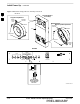
1 Close the battery shelf circuit breakers (Figure 2-3) for connected batteries only. This process should
be completed quickly to avoid individual battery strings drawing excess charge current
NOTE
If the batteries are sufficiently discharged, the battery circuit breakers may not engage individually
due to the surge current. If this condition occurs, disconnect the batteries from the 27Vdc bus by
setting the MAP power switch to OFF, and then engage all the connected battery circuit breakers.
The MAP power switch should then be turned ON.
2
Using the clamp–on DC current probe and DMM, measure the current in each of the battery string
connections to the battery bus bars. The charge current may initially be high but should quickly
reduce in a few minutes if the batteries have a typical new–battery charge level.
NOTE
The MAP AMP display will indicate the total current output of the rectifiers during this procedure.
As an alternative, the bar graph meters on the AC rectifier modules can be used as a rough estimate of
the total battery charge current. Each rectifier module bar graph has eight (8) LED elements to
represent the output current. Each illuminated LED element indicates that approximately 12.5% (1/8
or 8.75 Amps) of an individual rectifier’s maximum current output (70 Amps) is flowing.
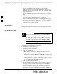
RECTIFIER BAR GRAPH EXAMPLE:
Question: A system fitted with three (3) rectifier modules each have three bar graph LED elements
illuminated. What is the total output current into the batteries?
Answer: Each bar graph is indicating approximately 12.5% of 70 amps, therefore, 3 x 8.75 equals
26.25 amps per rectifier. As there are three rectifiers, the total charge current is equal to (3 x 26.25 A)
78.75 amps.
This charge current calculation is only valid when the RF and LPA compartment electronics are not
powered on, and the RF compartment heat exchanger is turned off. This can only be accomplished if
the DC PDA MAIN BREAKER is set to OFF.
. . . continued on next page
2