
User's Manual

Initial Power Up – continued
PRELIMINARY
1X SCt4812ET Lite BTS Optimization/ATP
08/01/2001
2-14
DC Power Application and
Testing
Table 2-6 lists the step–by–step instructions for applying DC power and
ensuring the DC power system components are correctly functioning.
Table 2-6: DC Power Application and Tests
Step Action
1 Be sure all DC PDA and battery shelf circuit breakers are OFF (pulled out).
2 Be sure the procedures in Table 2-3 (if applicable) and Table 2-5 have been performed.
3
! CAUTION
When measuring voltage at the VOLT TEST POINTS, be careful not to short either of the test points
to ground. Failure to comply will result in severe damage to the MAP.
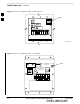
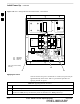
Measure voltage at the MAP VOLT TEST POINTS while pressing the 25° C SET button
(Figure 2-9). The voltage should read 27.4 +
0.2 Vdc. Adjust with the MASTER VOLTAGE ADJ. on
the MAP, if necessary, to obtain an indicated 27.4+
0.2 Vdc. Release the 25° C SET button.
4 Depending on the ambient temperature, the voltage reading may now change by up to + 1.5 V
compared to the reading just measured. If it is cooler than 25_C, the voltage will be higher, and if it is
warmer than 25_C, the voltage will be lower.
5 Inside the battery compartment, measure the voltage between the cable connection point at the bottom
of the + (red) battery bus bar and chassis ground, observing that the polarity is correct. The voltage
should be the same as the measurement in step 4.
6 Measure the voltage between the + (red) and – (black) battery bus bars in the battery compartment.
Place the probe at the bottom of the bus bars where the cables are connected. The DC voltage should
measure the same as in step 4.
7 Close (push in) DC PDA MAIN BREAKER.
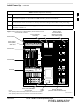
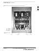
8 On the DC PDA(Figure 2-6), set the PS1 and PS2 circuit breakers to the ON position by pushing
them in one at a time while observing the rectifier output current indicated on the MAP AMP display.
– The display should indicate between 20 and 60 amps.
9 On the DC PDA), set the remaining circuit breakers to the ON position by pushing them in one at a
time in the following sequence:
S LPA circuit breakers (four breakers, labeled 1A–1B through 3C–3D).
S HEAT EXCHANGER circuit breakers (two breakers)
S ETIB circuit breaker
S PILOT BEACON circuit breaker
S OPTION circuit breaker
. . . continued on next page
2