
User's Manual

Initial Power Up – continued
PRELIMINARY
1X SCt4812ET Lite BTS Optimization/ATP
08/01/2001
2-8
Table 2-3: DC Power System Pre–Power Application Test
Step Action
4
* IMPORTANT
Do not unseat the AC rectifier modules in the following step.
Perform the following:
S In the frame RF compartment, unseat all circuit boards/ modules (except CCD and CIO cards) in the
SCCP shelf, but leave them in their respective slots.
S In the frame LPA compartment, disconnect the Linear Power Amplifier (LPA) cables from the
compartment bulkhead feed through connector.
5 Set the DMM to measure resistance, and inside the battery compartment, measure the resistance
between the + (red) and – (black) battery bus bars. The resistance should measure >
1 ΜΩ.
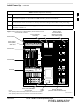
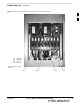
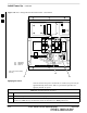
6 Leave the DMM set to measure resistance, and insert the probes into the MAP VOLT and AMP TEST
POINTS (Figure 2-9). Place the (+) DMM probe into the (–) AMP TEST POINT. Place the (–) DMM
probe into the (–) VOLT TEST POINT. Resistance should measure greater than 750 Ω.
7 On the DC PDA, set the MAIN BREAKER to the ON position by pushing it in. Resistance between
the MAP (–) VOLT TEST POINT and the (–) AMP TEST POINT should measure between 300 Ω.
minimum 900 Ω. maximum.
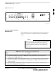
8
Before proceeding, be sure the SCCP shelf power/converter modules PS1 and PS2 are correct by
verifying that the locking/retracting tabs appear as follows:
–
(in +27 volt systems)
! CAUTION
Using the incorrect type of power/converter modules will damage the module, the SCCP shelf, and
other modules installed in the SCCP shelf.
9
* IMPORTANT
In the following steps, if the DMM reads between 300 Ω minimum and 900 Ω maximum after
inserting any board/module, a low impedance problem probably exists in that board/module. Replace
the suspect board/module and repeat the test. If test still fails, isolate the problem before proceeding.
Insert and lock the PS1 DC–DC converter module into its slot, and and turn ON the PS1 DC circuit
breaker on the DC PDA.
10 Resistance between the MAP (–) VOLT TEST POINT and the (–) AMP TEST POINT should
typically increase as capacitors charge, finally measuring between 300 Ω minimum and 900 Ω.
maximum.
11 Repeat steps 9 and 10 for the PS2 converter module/circuit breaker and all other remaining modules in
the SCCP shelf.
12 On the DC PDA, set the LPA 1A–1B circuit breaker to the ON position by pushing it in, and repeat
step 10.
13 Repeat step 12 for each of the three remaining LPA circuit breakers.
. . . continued on next page
2