
User's Manual

Initial Power Up – continued
08/01/2001
2-5
1X SCt4812ET Lite BTS Optimization/ATP
PRELIMINARY
Table 2-2: Initial Inspection and Setup
Step Action
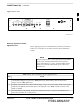
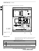
3 Confirm that the Meter Alarm Panel (MAP) POWER switch and all LEDs (Figure 2-9) are OFF. If
any LEDs are lighted, re–check and turn OFF all battery shelf circuit breakers.
4 If a heat source was placed in the RF compartment to prevent condensation prior to BTS power–up,
turn off the heat source and remove it and any associated cabling from the BTS before proceeding.
5 Confirm that the external 220 Vac supply is correctly connected to the ACLC input by performing the
procedure in Table 2-4.
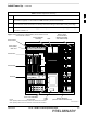
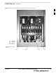
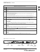
Figure 2-3: Frame Power Subassemblies, North American and
International Cabinets
LPAs
SCCP Fans
RFDS
SCCP Shelf
ETIB
Meter Alarm
Panel (MAP)
With TCU
AC Rectifiers
DC PDA
Backup Batteries
(Heaters underneath batteries)
External Blower
Assembly
SC4812ETL0002–3
Battery Shelf
Circuit Breakers
(Between Bus Bar
and Cabinet Wall)
Utility
Outlet
ACLC Circuit Breaker
Access Door
NOTE:
GFCI capability is built into the Utility Outlet of the North American Cabinet.
GFCI capability is built into the circuit breakers of the International Cabinet
2