
User's Manual

Initial Power Up
PRELIMINARY
1X SCt4812ET Lite BTS Optimization/ATP
08/01/2001
2-4
Introduction
The following information is used to check for any electrical short
circuits and to verify the operation and tolerances of the cell site and
BTS power supply units before applying power for the first time. It
contains instructional information on the proper initial power up
procedures for the SC4812ET Lite for both the North American version
and the International version. If directions are different for either version,
they are called out within the procedure. Please pay attention to all
cautions and warning statements in order to prevent accidental injury to
personnel.
Required Tools
The following tools are used in the procedures.
S Clamp–on DC current probe (600 amp capability with jaw size to
accommodate 2/0 cable).
S Digital Multimeter (DMM) with standard 2mm (.080”) tip probes
S Hot Air Gun – (optional for part of the Alarm Verification)
Cabling Inspection
Using the site-specific documentation generated by Motorola Systems
Engineering, verify that the following cable systems are properly
connected:
S Receive RF cabling – up to six RX cables
S Transmit RF cabling – up to six TX cables
For DC power applications (+27 V):
S The positive power cable is red.
S The negative power cable is black. (The black power
cable is at ground potential.)
IMPORTANT
*
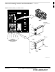
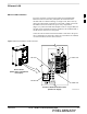
Initial Inspection and Setup
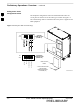
Ensure all battery shelf circuit breakers (Figure 2-3) for
unused battery positions are off (pulled out) before and
during the entire power up process. Leave these breakers in
the off position when leaving the site.
CAUTION
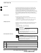
Table 2-2: Initial Inspection and Setup
Step Action
1 Be sure that the facility circuit breaker controlling external AC power supplied to the frame is set to
OFF.
2 Be sure that all AC Load Center (ACLC), all DC Power Distribution Assembly (PDA), and all battery
shelf circuit breakers are turned OFF.
. . . continued on next page
2