
User's Manual
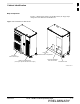
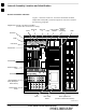

Internal Assembly Location and Identification – continued
PRELIMINARY
1X SCt4812ET Lite BTS Optimization/ATP
08/01/2001
1-22
FILLER
POWER 1 POWER 2
HSO/LFR CSM 1 CSM 2
CCD
AMR GLI2
1 2
3 4
MCC
1 2 3
4 5 6
BBX2
R1
SWITCH
1
2
1
2
1
2
MPC
FILLER
POWER 1 POWER 2
HSO/LFR CSM 101 CSM 102
CCD
AMR
GLI2
101 102
MCC
101 102 103
BBX2
R101
SWITCH
102
1
2
MPC
101
101
102 103 104 104 105 106
MPC
CSM
Power Supply
Power Supply
MPC
CSM
CCDCCD
AMR
HSO
AMR
GLI2 GLI2
MCC8 E or MCC24
BBX2
BBX2
BBX2
BBX2
BBX2
BBX2
SWITCH
19mm Filler Panel
BBX2
CIO
FRAME 1
FRAME 101
(Expansion Frame)
MCC8 E or MCC24 MCC8 E or MCC24
MCC8 E or MCC24
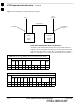
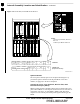
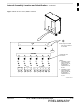
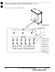
Figure 1-5: SCCP Shelf, IS–95A/B and 1X Devices
SC4812ETL0003–4
NOTES:
1. MCCs may be MCC8Es, MCC24s, or
MCC–1Xx
2. BBXx may be BBX2s or BBX–1Xs
Span I/O Boards
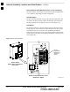
The two span I/O boards, Span I/O A and Span I/O B (Figure 1-3),
provide the span line interface from the punchblock or the CSU
modules, if equipped, to the SCCP backplane.
Transmit & receive, non–duplexed, Receive filter, Dual
Directional Coupler (TRDC)
TRDCs provide separate, bandpass–filtered sector transmit and receive
paths. When TRDCs are used separate transmit and receive antennas are
required for each sector. As with DRDCs, TRDCs dual directional
couplers for each antenna path which permit signal monitoring by the
RFDS.
1