
User's Manual

Internal Assembly Location and Identification – continued
PRELIMINARY
1X SCt4812ET Lite BTS Optimization/ATP
08/01/2001
1-20
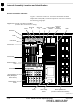
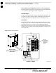
Filter/Combiner Shelf (Bandpass Filters or 2:1 Combiners)
The filter/combiner shelf (Figure 1-3) holds the transmit bandpass filters
or 2:1 combiners, depending on system configuration.
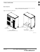
Heat Exchanger
The heat exchanger provides cooling to the frame RF compartment. The
fan speed of the heat exchanger adjusts automatically with temperature.
The heat exchanger is located in the frame main door (Figure 1-2).
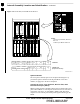
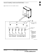
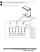
Punchblock
The punchblock (Figure 1-4) is the interface between the frame and the
T1/E1 span lines. It is located on the right–hand side of the power entry
compartment at the rear of the frame. The punchblock provides the
initial interconnection between the spans and the Customer–defined I/O,
alarms, multi–frame timing source (RGPS and RHSO), and pilot beacon
control (optional).
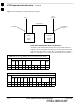
Figure 1-4: 50–Pair Punchblock
SC4812ETL0024–1
Rear of Frame
(Power Entry Compartment
Door Open)
Section of Network Interface Panel
(Rotated 30_ Right)
50–Pin
Punchblock
(Cabling not
shown for
clarity)
1