
User's Manual

Internal Assembly Location and Identification – continued
08/01/2001
1-19
1X SCt4812ET Lite BTS Optimization/ATP
PRELIMINARY
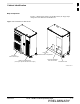
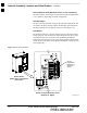
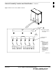
AC Load Center (ACLC)
The ACLC is the frame entry point for AC power. It incorporates AC
power control, distribution, and surge protection (Figure 1-3).
Back–up Batteries
The batteries (Figure 1-3) provide +24 Vdc back–up for the frame should
AC power be interrupted. The frame can accommodate a total of 12 12V
batteries grouped in six strings. Each string consists of two batteries
connected in series for 24 Vdc output. The six strings are connected in
parallel to meet the current–draw requirements of the frame. The
maximum time duration of the back–up capability depends on system
configuration.
Battery Heaters
The battery heater pads warm the batteries to provide improved
cold–weather performance. A separate heater pad is required for each
battery string and is located between each battery string and its
respective support shelf.
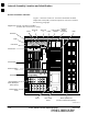
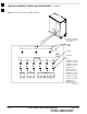
Channel Service Units (CSU) (Optional)
The SC4812ET Lite can be equipped with up to two M–PAT H 537 CSU
or two M–PATH 437 CSU modules which install in the CSU shelf
(Figure 1-3). These modules allow monitoring of span performance and
provide capability for remote network management.
CSU Shelf
The CSU shelf is an ADC Kentrox 2–slot Universal Shelf which can
accommodate two M–PATH 537 or two M–PATH 437 CSU modules.
When the optional CSU modules are not installed, cover plates are
installed over the CSU card slots (Figure 1-3).
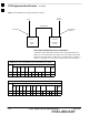
DC Power Distribution Assembly (PDA)
Both rectifier output voltage and back–up battery voltage are routed to
the PDA (Figure 1-3) where they are combined into system DC bus
voltage. The PDA provides distribution of DC power and system DC
bus protection from the loads with MAIN BREAKER and the smaller
post–distribution circuit breakers. MAIN BREAKER permits removal of
all frame loading from the bus. The 13 post–distribution circuit breakers
permit removal of individual loads.
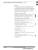
Duplexer, Receive filter, Dual Directional Coupler (DRDC)
DRDCs permit duplexing of sector transmit and receive signals on a
single antenna. The DRDCs also incorporate a receive bandpass filter
and dual directional couplers which permit signal monitoring by the RF
Diagnostic Subsystem.
ET Interface Board (ETIB) and LPA Control (LPAC) Board
The ETIB is an interconnect module with status LEDs, MMI recepticles,
and secondary surge protection for the LPA modules. The LPAC board
provides the interface for the LPA connections (Figure 1-3).
1