
User's Manual

Alarms Testing68P09255A69-3
Aug 2002
1X SC4812ET Lite BTS Optimization/ATP Software Release 2.16.1.x
PRELIMINARY
3-105
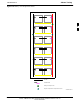
Single Rectifier Failure (Three Rectifier System)
Table 3-58 gives instructions on testing single rectifier failure or minor
alarm in a three (3) rectifier system (single-carrier system). Procedures
in this test are for a frame configured for single carrier operation with
rectifiers installed in rectifier shelf positions 1, 2, and 3, from left to
right when facing the frame.
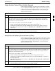
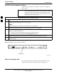
Table 3-58: Single Rectifier Fail or Minor Alarm, Single-Carrier System
Step Action
1
! CAUTION
Only perform this test if the rectifier current load displayed on the AMP indicator on the MAP is
125 amps or less. Sufficient current capability to support a greater load may not be available when
one rectifier is removed from the bus.
On the ACLC, set the RECT. 2/4 circuit breaker to OFF.
- The DC and PWR LEDs should light red on the rectifier in shelf position 2.
- The MINOR ALARM (amber) and RECTIFIER FAIL (red) LEDs on the MAP should light.
- The LMF should report an alarm condition as BTS Relay #21 and BTS Relay #24 contacts,
respectively.
2 Set the RECT. 2/4 circuit breaker on the ACLC to ON.
- All alarm indications should clear on the rectifier, MAP, and LMF.
Multiple Rectifier Failure (Three Rectifier System)
Table 3-59 gives instructions on testing multiple rectifier failure or major
alarm in a three (3) rectifier system (single-carrier system). Procedures
in this test are for a frame configured for single carrier operation with
rectifiers installed in rectifier shelf positions 1, 2, and 3, from left to
right when facing the frame.
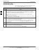
Table 3-59: Multiple Rectifier Failure or Major Alarm, Single-Carrier System
Step Action
1
! CAUTION
Only perform this test if the rectifier current load displayed on the AMP indicator on the MAP is 65
amps or less. Sufficient current capability to support a greater load may not be available when two
rectifiers are removed from the bus.
On the ACLC, set the RECT. 1/3 circuit breaker to OFF.
- The DC and PWR LEDs should light red on the rectifiers in shelf positions 1 and 3.
- The MAJOR ALARM (red), MINOR ALARM (amber), and RECTIFIER FAIL (red) LEDs on
the MAP should light.
- The LMF should report an alarm condition as BTS Relay #21, BTS Relay #24, and BTS Relay
#29 contacts, respectively.
2 Set the RECT. 1/3 circuit breaker on the ACLC to ON.
- All alarm indications should clear on the rectifiers, MAP, and LMF.
3