
User's Manual

Alarms Testing68P09255A69-3
Aug 2002
1X SC4812ET Lite BTS Optimization/ATP Software Release 2.16.1.x
PRELIMINARY
3-103
Alarm Testing Set-up
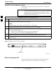
Prepare for any alarm testing by following the procedures in Table 3-53.
Table 3-53: Alarm Testing Preparation
Step Action
1 If it has not already been done, refer to the procedure in Table 3-10 to connect the LMF computer
terminal to the frame LAN A connector.
2 If it has not already been done, refer to Table 3-11 to start a GUI LMF session.
3 Click on Util in the BTS menu bar, and select Alarm Monitor... from the pull-down menu.
- An Alarm Monitor window will open.
Heat Exchanger Alarm Test
Table 3-54 gives instructions on testing the Heat Exchanger alarm.
Table 3-54: Heat Exchanger Alarm
Step Action
1 Set one of the two DC PDA heat exchanger circuit breakers to OFF. This will generate a heat
exchanger alarm. Be sure that the LMF reports the correct alarm condition.
2 Alarm condition will be reported as BTS Relay #14, BTS Relay #15, BTS Relay #16, BTS Relay
#17, BTS Relay #18, with Contact Alarm Open*Clear*, respectively.
3 Set the circuit breaker turned off in step 1 to ON. Ensure that the alarm conditions have cleared on
the LMF with Contact Alarm Closed*Clear* for each reported BTS relay.
NOTE
The heat exchanger will go through the start-up sequence.
Door Alarm
Table 3-55 gives instructions on testing the door alarms.
Table 3-55: ACLC and Power Entry Door Alarm
Step Action
1 Close the ACLC and power entry compartment doors on the frame. Ensure that no alarms are reported
on the LMF.
2 Individually open and then close the ACLC and power entry compartment door. Ensure that the LMF
reports an alarm when each door is opened.
3 Alarm condition will be reported as BTS Relay #27 contact.
3