
User's Manual

Test Set Calibration68P09255A69-3
Aug 2002
1X SC4812ET Lite BTS Optimization/ATP Software Release 2.16.1.x
PRELIMINARY
3-69
Calibrating Test Equipment
The LMF Calibrate Test Equipment function zeros the power
measurement level of the test equipment item that is to be used for TX
calibration and audit. If both a power meter and an analyzer are
connected (for example, an HP 437 and an HP8921A/600), only the
power meter is zeroed.
NOTE
The Agilent E4406A transmitter tester does not support power
measurement level zeroing. Refer to the Equipment Calibration
section of Appendix F for E4406A calibration.
Prerequisites
LMF computer serial port and test equipment are connected to the
GPIB box.
Test equipment is turned on and has warmed up for at least 60
minutes.
Test equipment has been selected in the LMF (Table 3-28 or
Table 3-29)
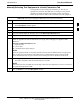
Follow the procedure in Table 3-30 to calibrate the test equipment.
Table 3-30: Test Equipment Calibration
Step Action
1 Click Util in the BTS menu bar, and select Calibrate Test Equipment from the pull-down menu.
-A Directions window will be displayed.
2 Follow the direction provided.
3 Click on Continue to close the Directions window and start the calibration process.
-A status report window is displayed.
4 Click on OK to close the status report window.
Calibrating Cables - Overview
The LMF Cable Calibration function is used to measure the path loss
(in dB) for the TX and RX cables, adapters, directional couplers, and
attenuators that make up the cable configurations used for testing. A
communications system analyzer is used to measure the loss of both the
TX test cable and the RX test cable configurations. LMF cable
calibration consists of the following processes:
1. Measure the loss of a short cable. This is done to compensate for any
measurement error of the communications system analyzer. The
short cable, which is used only for the calibration process, is
connected in series with both the TX and RX test cable
configurations when they are measured. The measured loss of the
short cable is deducted from the measured loss of the TX and RX
test cable configurations to determine the actual loss of the
configurations. This deduction is done so any error in the analyzer
measurement will be adjusted out of both the TX and RX
measurements.
3