
User's Manual

Test Equipment Set-up
68P09255A69-3
Aug 2002
1X SC4812ET Lite BTS Optimization/ATP Software Release 2.16.1.x
PRELIMINARY
3-48
Test Equipment Set-up
Connecting Test Equipment to the BTS
The following types of test equipment are required to perform calibration
and ATP tests:
LMF
Communications system analyzer model supported by the LMF
Power meter model supported by the LMF (required when using the
HP 8921A/600 and Advantest R3465 analyzers)
Non-radiating transmit line termination load
Directional coupler and in-line attenuator
RF cables and adapters
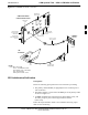
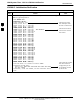
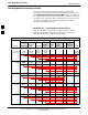
Refer to Table 3-26 for an overview of connections for test equipment
currently supported by the LMF. In addition, see the following figures:
Figure 3-13, Figure 3-14, and Figure 3-15 show the test set
connections for TX calibration
Figure 3-16 through Figure 3-21 show the test set connections for
optimization/ATP tests
Test Equipment GPIB Address Settings
All test equipment is controlled by the LMF through an IEEE-488/GPIB
bus. To communicate on the bus, each piece of test equipment must have
a GPIB address set which the LMF will recognize. The standard address
settings used by the LMF for the various types of test equipment items
are as follows:
Signal generator address: 1
Power meter address: 13
Communications system analyzer: 18
Using the procedures included in the Setting GPIB Addresses section of
Appendix NO TAG, verify and, if necessary, change the GPIB address of
each piece of employed test equipment to match the applicable addresses
above
.
3