
User's Manual

CSM System Time - GPS & LFR/HSO Verification68P09255A69-3
Aug 2002
1X SC4812ET Lite BTS Optimization/ATP Software Release 2.16.1.x
PRELIMINARY
3-41
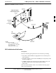
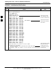
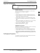
Figure 3-9: CSM MMI Terminal Connection
NULL MODEM
BOARD
(TRN9666A)
RS-232 SERIAL
MODEM CABLE
DB9-TO-DB25
ADAPTER
COM1
LMF
NOTEBOOK
FW00372
CSM card shown
removed from frame
19.6 MHZ TEST
POINT REFERENCE
(NOTE 1)
EVEN SECOND
TICK TEST POINT
REFERENCE
GPS RECEIVER
ANTENNA INPUT
GPS RECEIVER
MMI SERIAL
PORT
ANTENNA COAX
CABLE
REFERENCE
OSCILLATOR
9-PIN TO 9-PIN
RS-232 CABLE
NOTES:
1. One LED on each CSM:
Green = IN-SERVICE ACTIVE
Fast Flashing Green = OOS-RAM
Red = Fault Condition
Flashing Green & Red = Fault
GPS Initialization/Verification
Prerequisites
Ensure the following prerequisites have been met before proceeding:
The primary CSM and HSO (if equipped) has been warmed up for at
least 15 minutes.
The LMF computer is connected to the MMI port of the primary CSM
as shown in Figure 3-9.
An MMI communication session has been started (Table 3-15), and
the
CSM> prompt is present in the HyperTerminal window
(Table 3-23).
Follow the steps outlined in Table 3-24 to initialize and verify proper
GPS receiver functioning.
3