Test Equipment Preparation – continued HP8921A System Connectivity Test Follow the steps outlined in Table F-3 to verify that the connections between the PCS Interface and the HP8921A are correct and cables are intact. The software also performs basic functionality checks of each instrument. IMPORTANT * Disconnect other GPIB devices, especially system controllers, from the system before running the connectivity software.
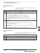
Test Equipment Preparation – continued Setting HP8921A and HP83236A/B GPIB Address Table F-4: Setting HP8921A GPIB Address Step Action 1 If you have not already done so, turn the HP8921A power on. 2 Verify that the GPIB addresses are set correctly. S HP8921A HP–IB Adrs = 18, accessed by pushing LOCAL and selecting More and I/O Configure on the HP8921A/600. (Consult test equipment OEM documentation for additional info as required). S HP83236A (or B) PCS Interface GPIB address=19.
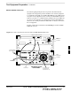
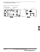
Test Equipment Preparation – continued Advantest R3465 Connection The following diagram depicts the rear panels of the Advantest test equipment as configured to perform automatic tests. All test equipment is controlled by the LMF via an IEEE–488/GPIB bus. The LMF expects each piece of test equipment to have a factory-set GPIB address (refer to Table F-7).
Test Equipment Preparation – continued Figure F-4 shows the connections when using an external 10 MHz Rubidium reference.
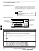
Test Equipment Preparation – continued R3465 GPIB Address & Clock setup Table F-7 describes the steps to set the GPIB address and clock for the Advantest R3465 equipment. Table F-7: Advantest R3465 GPIB Address and Clock Setup Step 1 Action Communications test set GPIB address=18 (perform the following to view/set as required) Perform the following to set the standard parameters on the test set: S Push the SHIFT then PRESET pushbutton (just below the CRT display).
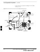
Test Equipment Preparation – continued Calibrating HP437 Power Meter Precise transmit output power calibration measurements are made using a bolometer–type broadband power meter with a sensitive power sensor. Follow the steps outlined in Table F-9 to enter information unique to the power sensor before calibrating the test setup. Refer to Figure F-5 as required. IMPORTANT * This procedure must be done in conjunction with the automated calibration to enter power sensor specific calibration values.
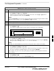
Test Equipment Preparation – continued Table F-9: Power Meter Calibration Procedure Step 4 Action Perform the following to set or verify the correct power sensor model: – Press [SHIFT] then [a] to select SENSOR. – Identify the power sensor model number from the sensor label. Use the [y] or [b] button to select the appropriate model; then press [ENTER]. NOTE Be sure the PWR REF (power reference) output is OFF (observe that the triangular indicator is NOT displayed as shown in Step 7).
Test Equipment Preparation – continued Calibrating Gigatronics 8542 power meter Precise transmit output power calibration measurements are made using a bolometer–type broadband power meter with a sensitive power sensor. Follow the steps in Table F-10 to enter information unique to the power sensor. Table F-10: Calibrate Gigatronics 8542 Power Meter Step Action ! CAUTION Do not connect/disconnect the power meter sensor cable with AC power applied to the meter.
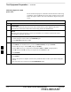
Test Equipment Preparation – continued Figure F-6: Gigatronics 8542C Power Meter Detail CONNECT POWER SENSOR TO CALIBRATOR POWER REFERENCE WHEN CALIBRATING/ZEROING UNIT CONNECT POWER SENSOR WITH POWER METER TURNED OFF AC POWER FRONT View GPIB CONNECTION REAR View FW00564 F 08/01/2001 1X SCt4812ET Lite BTS Optimization/ATP PRELIMINARY F-13
Manual Cable Calibration Calibrating Test Cable Setup using HP PCS Interface (HP83236) Table F-11 covers the procedure to calibrate the test equipment using the HP8921 Cellular Communications Analyzer equipped with the HP83236 PCS Interface. NOTE This calibration method must be executed with great care. Some losses are measured close to the minimum limit of the power meter sensor (–30 dBm).
Manual Test Cable Setup – continued Table F-11: Calibrating Test Cable Setup (using the HP PCS Interface) Step Action 8 Set RF Generator level: – Position the cursor at RF Generator Level and select it. – Enter –10 using the numeric keypad; press [Enter] and the screen will go blank. – When the screen reappears, the value –10 dBm will be displayed on the RF Generator Level line.
Manual Test Cable Setup – continued Table F-11: Calibrating Test Cable Setup (using the HP PCS Interface) Step Action 19 After all components are calibrated, reassemble all components together and calculate the total test setup loss by adding up all the individual losses: S Example: Total test setup loss = –1.4 –29.8 –20.1 = –51.3 dB. This calculated value will be used in the next series of tests. 20 Under Screen Controls press the TESTS button to display the TESTS (Main Menu) screen.
Manual Test Cable Setup – continued Figure F-7: Cable Calibration Using HP8921 with PCS Interface MEMORY CARD SLOT POWER SENSOR (A) (A) POWER SENSOR (B) F (B) 20 dB / 20 WATT ATTENUATOR POWER SENSOR (C) POWER SENSOR (C) 50 Ω TERMINATION 150 W NON–RADIATING RF LOAD 08/01/2001 30 dB DIRECTIONAL COUPLER FW00292 1X SCt4812ET Lite BTS Optimization/ATP PRELIMINARY F-17
Manual Test Cable Setup – continued Calibrating Test Cable Setup using Advantest R3465 NOTE Be sure the GPIB Interface is OFF for this procedure. Advantest R3465 Manual Test setup and calibration must be performed at both the TX and RX frequencies. Table F-12: Procedure for Calibrating Test Cable Setup Using Advantest R3465 Step Action * IMPORTANT – This procedure can only be performed after test equipment has been allowed to warm–up and stabilize for a minimum of 60 minutes.
Manual Test Cable Setup – continued Table F-12: Procedure for Calibrating Test Cable Setup Using Advantest R3465 Step 16 Action Disconnect the power meter sensor from the R3561L RF OUT jack. * IMPORTANT The Power Meter sensor’s lower limit is –30 dBm. Thus, only components having losses < 30 dB should be measured using this method. For best accuracy, always re–zero the power meter before connecting the power sensor to the component being calibrated.
Manual Test Cable Setup – continued Figure F-8: Cable Calibration Using Advantest R3465 RF OUT POWER SENSOR (A) & (B) POWER SENSOR F (C) 20 DB / 2 WATT ATTENUATOR POWER SENSOR (C) POWER SENSOR (D) FW00320 50 Ω TERMINATION 100 W NON–RADIATING RF LOAD F-20 30 DB DIRECTIONAL COUPLER 1X SCt4812ET Lite BTS Optimization/ATP 08/01/2001 PRELIMINARY
Appendix G: Download ROM Code Appendix Content Downloading ROM Code with the LMF . . . . . . . . . . . . . . . . . . . . . . . . . . . . . . Exception Procedure – Downloading Device ROM Code . . . . . . . . . .
Table of Contents – continued Notes F 1X SCt4812ET Lite BTS Optimization/ATP 08/01/2001 PRELIMINARY
Downloading ROM Code with the LMF Exception Procedure – Downloading Device ROM Code This procedure is not part of a normal optimization. Perform this procedure only on an exception basis when no alternative exists to load a BTS device with the correct version of ROM code. NOTE An MGLI or GLI must be INS (green) before ROM code can be downloaded to non–GLI devices. CAUTION Release 2.9.x RAM code must NOT be downloaded to a device loaded with Release 2.8.x ROM code, and Release 2.8.
Downloading ROM Code with the LMF – continued CAUTION The Release level of the ROM code to be downloaded must be the same as the Release level of the ROM code resident in the other devices in the BTS. Release 2.9.x ROM code must not be downloaded to a frame having Release 2.8.x code, and Release 2.8.x code must not be downloaded to a frame having Release 2.9.x code. This procedure should only be used to upgrade replacement devices for a BTS. It should NOT be used to upgrade all devices in a BTS.
Downloading ROM Code with the LMF – continued Table G-1: Download ROM and RAM Code to Devices Step Action ! CAUTION A ROM code file with the correct hardware binary type (HW Bin Type) must be chosen. Using a file with the wrong HW Bin Type can result in unpredictable operation and damage to the device. 9 Click on the ROM code file with the filename which matches the device type and HW Bin Type number noted in step 3 (e.g., file bbx_rom.bin.0604 is the ROM code file for a BBX with a HW Bin Type of 0604).
Downloading ROM Code with the LMF – continued Notes F G-4 1X SCt4812ET Lite BTS Optimization/ATP 08/01/2001 PRELIMINARY
Appendix H: In–Service Calibration Appendix Content Introduction . . . . . . . . . . . . . . . . . . . . . . . . . . . . . . . . . . . . . . . . . . . . . . . . . . . . . Purpose . . . . . . . . . . . . . . . . . . . . . . . . . . . . . . . . . . . . . . . . . . . . . . . . . Equipment Warm up . . . . . . . . . . . . . . . . . . . . . . . . . . . . . . . . . . . . . . . 1X Test Equipment Requirements . . . . . . . . . . . . . . . . . . . . . . . . . . . . . H-1 H-1 H-1 H-1 Power Delta Calibration . . .
Table of Contents – continued Notes H 08/01/2001 PRELIMINARY 1X SCt4812ET Lite BTS Optimization/ATP
Introduction Purpose This procedure is a guide to performing calibration of new BTS expansion carriers while the system remains in service. This procedure also supports BTS recalibration following replacement of RF chain components while the remainder of the site stays in service. Motorola recommends performing this procedure during a maintenance window. This procedure cannot be performed on BTSs with 2–to–1 combiners. The procedure can only be performed on one side of the BTS at one time.
Introduction – continued IMPORTANT * IS–95A/B communication test sets such as the HP8921A/600 and Advantest R3561L can not calibrate 1X carrier functions. Calibration and test set–up for the HP 8921A/600 and Advantest R3561L test sets is included only for situations where it is necessary to use them for calibration of IS–95A/B mode operation.
Power Delta Calibration Power Delta Calibration Introduction The ISC procedure has several differences from a normal calibration procedure. One of these is the use of a spectrum analyzer/communications test set instead of a power meter to measure power. Power meters are broadband measurement devices and cannot be used to measure power during ISC because other carriers are operating. A spectrum analyzer can be used because it measures power at a given frequency.
Power Delta Calibration – continued Table H-1: Agilent E4406A Power Delta Calibration Procedure Step Action 4 On the E4432B, press RF On/Off to toggle the RF output to RF ON. – Note that the RF On/Off status in the screen display changes. 5 Measure and record the value reading on the HP437 power meter as result A____________________. 6 On the E4432B, press RF On/Off to toggle the RF output to RF OFF. – Note that the RF On/Off status in the screen display changes.
Power Delta Calibration – continued Table H-1: Agilent E4406A Power Delta Calibration Procedure Step Action 12 Calculate the Power Calibration Delta value. The delta value is the power meter measurement minus the Agilent measurement. Delta = A – B Example: Delta = –0.70 dBm – (–1.25 dBm) = 0.55 dBm Example: Delta = 0.26 dBm – 0.55 dBm = –0.29 dBm These examples are included to show the mathematics and do not represent actual readings.
Power Delta Calibration – continued Advantest R3267 Power Delta Calibration The Advantest R3267 spectrum analyzer and R3562 signal generator test equipment combination can be used for ISC of IS–2000 CDMA 1X as well as IS–95A/B operation modes. The power delta calibration is performed on the R3267. After the offset value has been calculated, add it to the TX cable loss value. Follow the procedure in Table H-2 to perform the Advantest R3267 Power Delta Calibration procedure.
Power Delta Calibration – continued Table H-2: Advantest R3267 Power Delta Calibration Procedure Step Action 17 Connect the RF cable from R3562 signal generator RF OUT port to the R3267 spectrum analyzer INPUT Port, refer to Figure H-4. 18 On the R3562 CRT, set the Output to ON by pressing ACTIVE key 6. 19 On the R3267, press the POWER key in the MEASUREMENT section of the control panel. 20 Press the LEVEL key in the ENTRY section of the control panel.
Power Delta Calibration – continued Table H-2: Advantest R3267 Power Delta Calibration Procedure Step Action 40 Calculate the Power Calibration Delta value. The delta value is the power meter measurement minus the Advantest measurement. Delta = A – B Example: Delta = –0.7 dBm – (–1.25 dBm) = 0.55 dB Example: Delta = 0.26 dBm – 0.55 dBm = –0.29 dBm These examples are included to show the mathematics and do not represent actual readings.
Power Delta Calibration – continued Agilent 8935 series E6380A Power Delta Calibration The Agilent E6380A (formerly HP8935) communications test set modified with either option 200 or R2K and E4432B signal generator test equipment combination can be used for ISC of IS–2000 CDMA 1X as well as IS–95A/B operation modes. The power delta calibration is performed on the E6380A. After the offset value has been calculated, add it to the TX cable loss value.
Power Delta Calibration – continued Table H-3: Agilent E6380A Power Delta Calibration Procedure Step Action 9 Set the E6380A as follows: – Measure mode to CDMA Anl – Frequency to the CDMA calibration target frequency – Input Attenuation to 0 dB – Input port to RF–IN – Gain to Auto – Anl Dir to Fwd 10 Turn on the E6380A signal output. 11 Set the Chn Pwr Cal to Calibrate and select to calibrate.
Power Delta Calibration – continued Figure H-6: Delta Calibration Setup – E6380A to E6380A Agilent E6380A DUPLEX OUT RF IN/OUT Short RF Cable FW00806 H 08/01/2001 1X SCt4812ET Lite BTS Optimization/ATP PRELIMINARY H-11
Power Delta Calibration – continued HP8921A Power Delta Calibration Use the HP8921A communications test set to measure power during ISC only for IS–95A and B operation of 800 MHz systems. After the offset value has been calculated, add it to the TX cable loss value. Follow the procedure in Table H-4 to perform the HP8921A Power Delta Calibration procedure. NOTE This procedure requires two HP8921A communication test sets.
Power Delta Calibration – continued Table H-4: HP8921A Power Delta Calibration Procedure Step Action 9 Set the measuring HP8921A as follows: – Measure mode to CDMA Anl – Frequency to the CDMA calibration target frequency – Input Attenuation to 0 dB – Input port to RF–IN – Gain to Auto – Analyzer Direction to Fwd 10 Turn on the source HP8921A signal output. 11 Measure and record the channel power reading on the measuring HP8921A as result B ________________________.
Power Delta Calibration – continued Figure H-8: Delta Calibration Setup – HP8921A to HP8921A Measurement HP8921A Source HP8921A DUPLEX OUT RF IN/OUT Short RF Cable FW00802 H H-14 1X SCt4812ET Lite BTS Optimization/ATP 08/01/2001 PRELIMINARY
Power Delta Calibration – continued Advantest R3465 Power Delta Calibration Use the Advantest R3465 spectrum analyzer to measure power during ISC only for IS–95A and B operation. After the offset value has been calculated, add it to the TX cable loss value. Follow the procedure in Table H-5 to perform the Advantest 3465 Power Delta Calibration procedure.
Power Delta Calibration – continued Table H-5: Advantest Power Delta Calibration Procedure Step Action 20 Press the dB/div CRT menu key. 21 Press the 10 dB/div CRT menu key. 22 Press the FREQ key in Entry area of the control panel. 23 Set the frequency to the desired value using the keypad entry keys. 24 Press the more 1/2 CRT menu key. 25 Press the Preselector CRT menu key to highlight 3.0G. 26 Press the FORMAT key in the Display Control area of the control panel.
Power Delta Calibration – continued Figure H-9: Delta Calibration Setup – R3561L to HP437 Advantest RF OUT R3561L Power Sensor HP437B Short RF Cable SENSOR FW00803 Figure H-10: Delta Calibration Setup – R3561L to R3465 RF OUT R3561L Short RF Cable R3465 INPUT FW00804 H 08/01/2001 1X SCt4812ET Lite BTS Optimization/ATP PRELIMINARY H-17
In–Service Calibration In–Service Calibration for 1X Upgrade IMPORTANT * This feature does NOT have fault tolerance at this time. The system has no safe–guards to prevent actions which will put the BTS out of service. If possible, perform this procedure during a maintenance window. Follow the procedures in this section precisely, otherwise the entire BTS will most likely go OUT OF SERVICE. At the CBSC, only perform operations on expansion hardware when it is in the OOS_MANUAL state.
In–Service Calibration – continued S An RFDS (or at a minimum a directional coupler), whose loss is already known, must be in line to perform the in–service calibration. S Test equipment has been calibrated after 1 hour warm up. S A short RF cable and two BNC–N adapters are available to perform Cable Calibration. S The Power Delta Calibration has been performed (see Table H-1, Table H-2, Table H-3, Table H-4, or Table H-5).
In–Service Calibration – continued Figure H-11: Optimization/ATP Test Setup Using Directional Coupler – Agilent Test Equipment TEST SETS Optimization/ATP SET UP NOTE: IF BTS RX/TX SIGNALS ARE DUPLEXED: BOTH THE TX AND RX TEST CABLES CONNECT TO THE DUPLEXED ANTENNA GROUP. Agilent E6380A (HP 8935) SYNC MONITOR EVEN SEC TICK PULSE REFERENCE FROM CSM BOARD FREQ MONITOR 19.
In–Service Calibration – continued Figure H-12: Optimization/ATP Test Setup Using Directional Coupler – Advantest R3267/R3562 Test Equipment TEST SETS Optimization/ATP SET UP NOTE: IF BTS RX/TX SIGNALS ARE DUPLEXED: BOTH THE TX AND RX TEST CABLES CONNECT TO THE DUPLEXED ANTENNA GROUP.
In–Service Calibration – continued Figure H-13: Optimization/ATP Test Setup Using RFDS – Agilent Test Equipment TEST SETS Optimization/ATP SET UP Agilent E6380A (HP 8935) SYNC MONITOR EVEN SEC TICK PULSE REFERENCE FROM CSM BOARD FREQ MONITOR 19.6608 MHZ CLOCK REFERENCE FROM CSM BOARD HP–IB TO GPIB BOX NOTE: IF BTS RX/TX SIGNALS ARE DUPLEXED: BOTH THE TX AND RX TEST CABLES CONNECT TO THE DUPLEXED ANTENNA GROUP.
In–Service Calibration – continued Figure H-14: Optimization/ATP Test Setup Using RFDS – Advantest R3267/R3562 Test Equipment TEST SETS Optimization/ATP SET UP Advantest R3267 (Top) and R3562 (Bottom) NOTE: IF BTS RX/TX SIGNALS ARE DUPLEXED: BOTH THE TX AND RX TEST CABLES CONNECT TO THE DUPLEXED ANTENNA GROUP. RX TEST CABLE TO EXT TRIG ON REAR OF SPECTRUM ANALYZER ANTENNA TX TEST CABLE COMMUNICATIONS TEST SET OUT TEST SET INPUT/ OUTPUT PORTS EXT REF IN EVEN SECOND/ SYNC IN RF IN 20 DB PAD (FOR 1.
In–Service Calibration – continued Follow the procedure in Table H-6 to perform the In–Service Calibration. Table H-6: In–Service Calibration Step Action * IMPORTANT Perform this procedure after test equipment has been allowed to warm–up and stabilize for a minimum of 60 minutes. 1 Set up the LMF for In–Service Calibration: – Start the LMF by double–clicking the LMF icon on the Windows desktop. – Click Tools > Options from the menu bar at the login screen.
In–Service Calibration – continued Table H-6: In–Service Calibration Step 4 Action Add the spectrum analyzer power delta to the TX Cable Loss. – Click Util > Edit > Cable Loss > TX. – Add the value computed in Table H-4, Table H-5, or Table H-3 to the TX Cable Loss. NOTE Be sure to include the sign of the value. The following examples are included to show the mathematics and do not represent actual readings: – Example: 5.65 dBm + 0.55 dBm = 6.20 dBm – Example: 5.65 dBm + (–0.29 dBm) = 5.
In–Service Calibration – continued Table H-6: In–Service Calibration Step 8 Action Download code and data to the target devices: – Click Tools > Update NextLoad > CDMA to set the code version that will be downloaded. – Check the appropriate code version in the pop up window and click the Save button to close. – Select the target BBX(s) on the C–CCP cage picture. – Click Device > Download Code/Data to start downloading code and data. ! CAUTION Perform the All Cal/Audit procedure on OOS devices only.
Index Numbers 10 MHz Rubidium Standard, optional test equipment, 1-11 10BaseT/10Base2 converter LMF to BTS connection, 3-21 remove from BTS, 5-4 2–way splitter, optional test equipment, 1-10 50–pair punchblock, 3-18 code domain power acceptance test procedure, 4-16 failure report generation, 4-20 FER test, frame error rate testing, 4-19 pilot time offset, 4-13 prerequisites, 4-2 spectral purity TX mask, 4-10 test matrix/detailed optimization, B-2 waveform quality (Rho), 4-12 waveform quality (RHO) accepta
Index – continued BTS Frame Erasure Rate.
Index – continued DC Power Problems, C–CCP Backplane Troubleshooting, 6-24 DC/DC Converter LED Status Combinations, 6-28 Detailed, optimization/ATP test matrix, B-2 Devices, download.
Index – continued HSO Initialization/Verification, 3-38 Logging Into a BTS, 3-23 Huber & Suhner, required test equipment, 1-9 Logging Out, 3-25 HyperTerminal, Creating named HyperTerminal connection, 3-7 LORAN–C Initialization/Verification, 3-46 HyperTerminal , create named connection, 3-7 LPA Module LED, 6-34 LPA errors, 6-9 LPA Shelf LED Status Combinations, 6-34 I I and Q values, E-1 M Initial HP8921A setup, F-14 Master Group Line Interface.
Index – continued CDMA subscriber mobile or portable radiotelephone, 1-11 duplexer, 1-10 frequency counter, 1-10 LAN tester, 1-10 oscilloscope, 1-10 RF circular, 1-11 RF test cable, 1-10 spectrum analyzer, 1-10 Oscilloscope, optional test equipment, 1-10 Prepare to leave the site bringing modules into service, 5-3 download code and data from CBSC, 5-3 Prerequisites, automated acceptance tests, 4-2 Procedures to Copy CAL Files From Diskette to the CBSC, 5-1, 6-2, 6-5, 6-6, 6-7 Procedures to Copy Files to
Index – continued RFDS Location, SC 4812ET, 1-25 Span line configuration, troubleshooting, 6-36 RFDS Test Subscriber Unit, 3-33 Span Line connector , 6-20 RFDS TSU Calibration Channel Frequencies, 3-83 SPANS LED, 6-31 Rho TX waveform quality acceptance test, 4-12 waveform quality requirements, 4-12 Spectral purity, TX mask – primary and redundant BBX, 4-7 ROM code described, 3-32 downloading, G-1 Spectrum analyzer, optional test equipment, 1-10 Spectral purity transmit mask, acceptance test, 4-1
Index – continued Timing reference cables, required test equipment Model SGLN1145A/4132A CSMs, 1-9 Model SGLN4132B CSMs, 1-9 TX Calibration Test, 3-72 tx fine adjust, E-1 TX Path Calibration, 3-66 Transmit TX path audit, 3-74 Transmit TX path calibration, 3-70 Troubleshooting DC Power Problems, 6-24 RF path fault isolation, 6-12 Set span configuration, 6-36 span problems, 6-35 TX and RX Signal Routing, 6-25 TX level accuracy fault isolation, 6-14 TX/RX OUT Connections, 4-2 U UNIX, shut down on LMF, 5-
Index – continued Notes Index-8 1X SCt4812ET Lite BTS Optimization/ATP 08/01/2001 PRELIMINARY
1X SCt4812ET Lite BTS Optimization/ATP Software Release 2.16.0.x and CDMA LMF Build 2.16.x.
1X SCt4812ET Lite BTS Optimization/ATP Software Release 2.16.0.x and CDMA LMF Build 2.16.x.