
User's Manual

Verify and Set Span Line Settings
JAN 2002
7-37
SC300 1X BTS Hardware Installation, ATP, and FRU Procedures
DRAFT
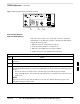
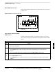
Objective
The following procedure is to verify and configure the BTS Span line
interface for T–1 or E–1 configurations.
Span Line Settings
The following are the span line settings for the BTS span line interface.
Span A: Primary span
Span B: Downstream span used for daisy–chaining.
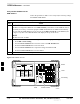
Procedure to Verify and Set
Span Line Settings
Use the procedure in Table 7-19 to verify and set (if necessary) the span
line settings.
Both spans A and B must be set to either T–1 or E–1. The
spans must match the parameters of the CBSC.
IMPORTANT
*
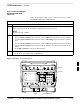
Table 7-19: Procedure to Verify and Set Span Line Settings
Step Action
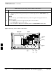
1 If you have not already done so, connect the LMF computer terminal to the MMI/LMF connector.
Refer to Table 7-7.
2 Open an MMI communications session. Refer to Table 7-6.
3 Enter the following command at the SC300> prompt to verify the current span settings:
span_config a
The system will display the following output:
Span A data:
Span type: 5 – T1_2 (B8ZS, DS1 AT&T ESF 4 to 1 packing, 64K link)
Link Speed: 64K
Span EQ: 0 – T1_6 (T1, J1:longhaul, same as choice 10)
LAPD slot: 0
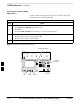
4 Enter the following command at the SC300> prompt to verify the current span settings:
span_config b
The system will display the following output:
Span B data:
Span type: 1 – E1_2 (HDB3)
Link Speed: 64K
Span EQ: 16 – E1 (Long haul: 120 Ohm)
LAPD slot: 1
. . . continued on next page
7