
User's Manual
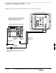


Connect Test Set and Power Meter to LMF – continued
JAN 2002
7-19
SC300 1X BTS Hardware Installation, ATP, and FRU Procedures
DRAFT
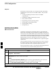
RS232 Cable Configuration
One National Instruments GPIB–232–CT with Motorola
CGDSEDN04X RS232 serial cable or equivalent is used to interface the
LMF to the test equipment.
A Standard RS–232 cable can be used with the following modifications:
Pin 8 (CTS) does not have to be jumpered/shorted to the others as it is
a driver output. The DTR is already a driver output signal. The other
pins are to receivers. Short pins 7, 1, 4, 6 on each cable end:
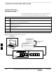
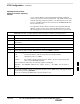
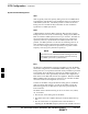
Figure 7-17 shows the cable configuration for the RS232–IEEE488
converter serial cable.
9–pin D (female) 9–pin D (female)
GND 5 5 GND
RX 3
3 RXTX 2
2 TX
RTS 7 7 RTS
RSD/DCD 1 1 RSD/DCD
DTR 4 4 DTR
DSR 6 6 DSR
Figure 7-17: RS232–IEEE488 Converter Serial Cable Configuration
CTS 8
8 CTS
ON BOTH CONNECTORS SHORT
PINS 7 AND 8;
SHORT PINS 1, 4 AND 6
7