
User's Manual


Connect Test Set and Power Meter to LMF
DRAFT
SC300 1X BTS Hardware Installation, ATP, and FRU Procedures
JAN 2002
7-18
Procedure to Connect the
Communication Test Set and
Power Meter to the LMF
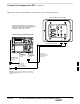
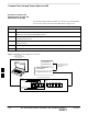
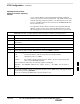
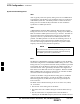
Use the following procedure in Table 7-5 to connect the communication
test set to the power meter and to the LMF. Refer to Figure 7-16.
Table 7-5: Procedure to Connect the Communication Test Set and Power Meter to the LMF
Step Action
1 Connect the RS232–IEEE488 converter serial cable between the COM1 port of the LMF and the
RS232 port of the RS232–IEEE488 converter.
2 Connect a GPIB cable between the RS232–IEEE488 converter and the GPIB port on the
communication test set.
3 Connect a GPIB cable between the GPIB port on the communication test set and the GPIB port of
the power meter.
4 Set the DIP switches on the RS232–IEEE488 converter as shown in Figure 7-16.
5 Power on the communication test set, power meter and RS232–IEEE488 converter.
Figure 7-16: LMF to Test Equipment Connection
LMF
OFF
ON
S MODE
DATA FORMAT
BAUD RATE
GPIB ADDRESS
G MODE
RS232–IEEE488 CONVERTER
GIGATRONICS
POWER METER
SIGNAL GENERATOR
(IF EQUIPPED)
COMMUNICATION TEST SET
GPIB CABLE(S) TO GPIB
CONNECTOR ON TEST
EQUIPMENT
RS–232 CABLE
TO COMM1 PORT ON CDMA
LMF NOTEBOOK
7