
User's Manual

Connect Test Equipment to BTS – continued
JAN 2002
7-11
SC300 1X BTS Hardware Installation, ATP, and FRU Procedures
DRAFT
In the following procedure and illustrations, typical DIP
switch positions and/or configurations are shown. If
required, refer to the test equipment OEM user manuals for
additional information.
NOTE
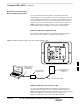
Procedure to Connect
Advantest R3465 to BTS
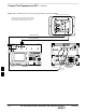
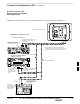
Follow the procedure in Table 7-3 to connect the Advantest R3465 to the
BTS. Refer to Figure 7-11.
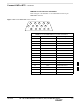
Table 7-3: Connecting Advantest R3465 to the BTS
Step Action
1 Connect an SMA/BNC coax cable between the following points:
– BNC on the Advantest CDMA TIMEBASE IN port.
– SMA on the 19 MHz port on the diagnostic access area of the BTS.
2 Connect an SMA/BNC cable between the following points:
– BNC to one end of the BNC “T.”
– SMA on the 2 Sec port on the diagnostic access area of the BTS.
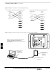
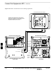
3 Connect a BNC/BNC cable between the following points:
– BNC to one end of the BNC “T.”
– BNC to the EXT TRIG port on the rear panel of the Advantest R3465.
4 Connect the BNC “T” to the EVEN SEC/SYNC IN port of the Advantest R356IL.
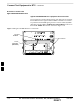
5 Verify the R3561 and R3465 rear panel connections are in place (These are common connections and
should already be installed):
– Serial cable between 3465A rear panel SERIAL I/O port and R3561 SERIAL I/O port.
– SMA cable between 3465A rear panel 1ST LO OUT port and R3561 LOCAL IN port.
7