
User's Manual

Full Unit Replacement Procedures – continued
DRAFT
SC300 1X BTS Hardware Installation, ATP, and FRU Procedures
JAN 2002
8-24
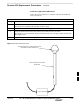
Install the replacement unit
Follow the steps in Table 8-15 to install the replacement unit.
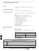
Table 8-15: Procedure to Install the New Unit
Step Action
1 Attach the installation handles to the replacement unit. Refer to the “Attaching Installation
Handles to Unit” procedure in Chapter 6.
2 Mount the replacement unit to the bracket. Refer to the “Attaching Unit to the Mounting
Bracket” procedure in Chapter 6.
3 Once the replacement unit has been secured to the mounting bracket, remove the installation
handles (reverse the installation order of the “Attaching Installation Handles to the Unit”
procedure in Chapter 6).
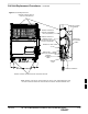
4 Attach the site I/O junction box or site I/O cap to the unit. Refer to the “Attaching the Site I/O
Junction Box to the Unit” procedure in Chapter 6 and Figure 8-4.
5 Attach the short duration battery (if present) to the unit. Refer to Table 8-9 in the “Short Duration
Battery Replacement Procedure” and NO TAG.
6 Connect the AC input cable. Refer to the “AC Power Cabling” procedure in Chapter 6.
7 Connect the DC input cable. Refer to the “DC Power Cabling” procedure in Chapter 6.
8 Connect the antenna cable(s). Refer to the “Antenna Cabling” procedure in Chapter 6.
9 Connect the MIB cables (if equipped). Refer to the “MIB Cabling” procedure in Chapter 6.
10 Connect the SU cables (if equipped). Refer to the “SU Cabling” procedure in Chapter 6.
11 Turn power on at the main power source (AC and/or DC).
12 If AC power is being supplied to the unit, close (push) the AC power breaker. The white collar on
the breaker is not visible when the breaker is closed.
13 If DC power is being supplied to the unit or if battery backup is present, close (push) the DC
power breaker. The white collar is not visible when the breaker is closed.
14 Perform the ATP, if necessary. Refer to the ATP procedures in Chapter 7.
15 Install the Solar Covers (if necessary).
16 Place the BTS back in service using the “Restore Signaling Operations” procedure in Table 8-3.
8