
User's Manual

Site I/O Junction Box Replacement Procedure – continued
JAN 2002
8-15
SC300 1X BTS Hardware Installation, ATP, and FRU Procedures
DRAFT
Remove the failed site I/O junction box
Follow the steps in Table 8-5 to remove the failed Site I/O junction box.
Table 8-5: Remove the Failed Site I/O Junction Box
Step Action
1 Place the BTS out of service using the “Shut Down Signaling Functions” procedure shown in
Table 8-2.
2 Using a T20 Torx tamper bit, remove the Solar Cover if one is present and locate the failed Site
I/O junction box.
3 If DC power is being supplied to the unit or if the battery backup is present, open (pull) the DC
power breaker. The white collar on the breaker is visible when the breaker is opened.
4 If AC power is being supplied to the unit, open (pull) the AC power breaker. The white collar on
the breaker is visible when the breaker is open.
5 Disconnect the unit ground cable from the Site I/O junction box.
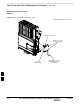
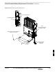
6 Using a T30 Torx tamper bit, remove the two tamper resistant captive screws to disconnect the
Site I/O junction box from the unit. See Figure 8-4.
7 If your BTS is equipped with the customer–supplied Site I/O interface, then proceed to step 8. If
your BTS is equipped with the optional Primary Surge Suppressor, then proceed to step 9.
8 Disconnect the Site I/O cable from the Deutsche connector on the Site I/O cable. Location of Site
I/O interface is site– dependent.
9 Disconnect the Site I/O cable from the Primary Surge Suppressor.
Install the replacement Site I/O junction box
Follow the steps in Table 8-6 to install the replacement Site I/O junction
box.
Table 8-6: Install the Replacement Site I/O Junction Box
Step Action
1 Reconnect the Site I/O cable according to the “Site I/O, Span Line, RGPS and Modem Cabling”
procedure in Chapter 4.
2 Install the replacement Site I/O junction box according to the “Mounting the Site I/O Junction
Box to the Unit” procedure in Chapter 5.
3 Attach the ground cable from the mounting bracket to the Site I/O junction box.
4 If AC power is being supplied to the unit, close (push) the AC power breaker. The white collar on
the breaker is not visible when the breaker is closed.
5 If DC power is being supplied to the unit or if battery backup is present, close (push) the DC
power breaker. The white collar on the breaker is not visible when the breaker is closed.
6 Install the Solar Cover if one is present according to the “Mounting Solar Cover and Powering on
Unit” procedure in Chapter 5.
7 Place the BTS back in service using the “Restore Signaling Operations” procedure in Table 8-3.
8