
User's Manual Part 2
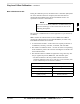

Bay Level Offset Calibration – continued
DRAFT
SC4812ET BTS Optimization/ATP — CDMA LMF
Apr 2001
3-64
Transmit (TX) Path Calibration
The assigned channel frequency and power level (as measured at the top
of the frame) for transmit calibration is derived from the site CDF file.
For each BBX2, the channel frequency is specified in the
ChannelList
CDF file parameter and the power is specified in the SIFPilotPwr
CDF file parameter for the sector associated with the BBX2 (located
under the
ParentSECTOR field of the ParentCARRIER CDF file
parameter).
The calibration procedure attempts to adjust the power to within +
0.5 dB
of the desired power. The calibration will pass if the error is less than
+
1.5 dB.
The TX Bay Level Offset at sites WITHOUT the directional coupler
option, is approximately 42.0 dB ±3.0 dB.
At sites WITHOUT RFDS option, BLO is approximately
42.0 dB ±4.0 dB. A typical example would be TX output power
measured at BTS (36.0 dBm) minus the BBX2 TX output level
(approximately –6.0 dBm) would equate to 42 dB BLO.
The TX Bay Level Offset at sites WITH the directional coupler option,
is approximately 41.4 dB ±3.0 dB. TX BLO = Frame Power Output
minus BBX2 output level.
Example: TX output power measured at RFDS TX coupler
(39.4 dBm) minus the BBX TX output level (approximately
–2.0 dBm) and RFDS directional coupler/cable (approximately
–0.6 dBm) would equate to 41.4 dB BLO.
The LMF Tests menu list items, TX Calibration and All Cal/Audit,
perform the TX BLO Calibration test for a XCVR(s). The All Cal/Audit
menu item performs TX calibration, downloads BLO, and performs TX
audit if the TX calibration passes. All measurements are made through
the appropriate TX output connector using the calibrated TX cable setup.
Prerequisites
Before running this test, ensure that the following have been done:
CSM–1,GLIs, MCCs, and BBX2s have correct code load and data
load.
Primary CSM and MGLI are INS.
All BBX2s are OOS_RAM.
Test equipment and test cables are calibrated and connected for TX
BLO calibration.
LMF is logged into the BTS.
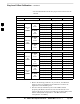
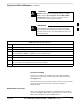
Connect the test equipment as shown in Figure 3-9 and Figure 3-10 and
follow the procedure in Table 3-33 to perform the TX calibration test.
3