
User's Manual Part 2

Test Set Calibration – continued
DRAFT
Apr 2001
3-55
SC4812ET BTS Optimization/ATP — CDMA LMF
Calibrating TX Cables Using a
Signal Generator and
Spectrum Analyzer
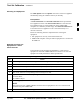
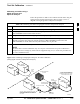
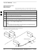
Follow the procedure in Table 3-26 to calibrate the TX cables using the
signal generator and spectrum analyzer. Refer to Figure 3-13 for a
diagram of the signal generator and spectrum analyzer.
Table 3-26: Calibrating TX Cables Using Signal Generator and Spectrum Analyzer
Step Action
1 Connect a short test cable between the spectrum analyzer and the signal generator.
2 Set signal generator to 0 dBm at the customer frequency of 1840–1870 MHz band for Korea PCS and
1930–1990 MHz band for North American PCS.
3 Use spectrum analyzer to measure signal generator output (see Figure 3-13, “A”) and record the value.
4 Connect the spectrum analyzer’s short cable to point “B”, as shown in the lower portion of the
diagram, to measure cable output at customer frequency (1840–1870 MHz for Korea PCS and
1930–1990 MHz for North American PCS) and record the value at point “B”.
5
Calibration factor = A – B Example: Cal = –1 dBm – (–53.5 dBm) = 52.5 dB
NOTE
The short cable is used for calibration only. It is not part of the final test setup. After calibration is
completed, do not re-arrange any cables. Use the equipment setup, as is, to ensure test procedures use
the correct calibration factor.
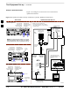
Figure 3-13: Calibrating Test Equipment Setup for TX Cable Calibration
(Using Signal Generator and Spectrum Analyzer)
50 OHM
TERMINATION
30 DB
DIRECTIONAL
COUPLER
Spectrum
Analyzer
Signal
Generator
A
Spectrum
Analyzer
40W NON–RADIATING
RF LOAD
B
SHORT TEST CABLE
Signal
Generator
THIS WILL BE THE CONNECTION TO THE
POWER METER DURING TX CALIBRATION
AND TO THE CDMA ANALYZER DURING TX
ATP TESTS.
SHORT
TEST
CABLE
THIS WILL BE THE CONNECTION
TO THE TX PORTS DURING TX
CALIBRATION AND TO THE TX/RX
PORTS DURING ATP TESTS.
SECOND RF
TEST CABLE.
ONE 20DB 20 W IN
LINE ATTENUATOR
FW00293
3