
User's Manual Part 2

Test Set Calibration – continued
DRAFT
Apr 2001
3-53
SC4812ET BTS Optimization/ATP — CDMA LMF
Calibrating Test Equipment
The calibrate test equipment function zeros the power measurement level
of the test equipment item that is to be used for TX calibration and audit.
If both a power meter and an analyzer are connected, only the power
meter is zeroed.
Calibrate Test Equipment from the Util menu list is used to calibrate
test equipment item before being used for testing. The test equipment
must be selected before beginning calibration. Follow the procedure in
Table 3-24 to calibrate the test equipment.
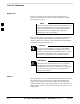
Table 3-24: Test Equipment Calibration
Step Action
1 From the Util menu, select Calibrate Test Equipment. A Directions window is displayed. Follow
the instructions provided.
2 Follow the direction provided.
3 Click on Continue to close the Directions window. A status window is displayed.
4 Click on OK to close the status report window.
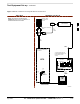
Calibrating Cables
The cable calibration function is used to measure the loss (in dB) for the
TX and RX cables that are to be used for testing. A CDMA analyzer is
used to measure the loss of each cable configuration (TX cable
configuration and RX cable configuration). The cable calibration
consists of the following steps.
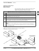
Measure the loss of a short cable. This is done to compensate for any
measurement error of the analyzer. The short cable, which is used only
for the calibration process, is used in series with both the TX and RX
cable configuration when they are measured. The measured loss of the
short cable is deducted from the measured loss of the TX and RX
cable configuration to determine the actual loss of the TX and RX
cable configurations. This deduction is done so any error in the
analyzer measurement will be adjusted out of both the TX and RX
measurements.
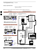
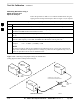
The short cable plus the RX cable configuration loss is measured. The
RX cable configuration normally consists only of a coax cable with
type–N connectors that is long enough to reach from the BTS RX port
the test equipment.
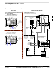
The short cable plus the TX cable configuration loss is measured. The
TX cable configuration normally consists of two coax cables with
type–N connectors and a directional coupler, a load, and an additional
attenuator if required by the BTS type. The total loss of the path loss
of the TX cable configuration must be as required for the BTS
(normally 30 or 50 dB). The Motorola Cybertest analyzer is different
in that the required attenuation/load is built into the test set so the TX
cable configuration consists only of the required length coax cable.
3