
User's Manual Part 2


CSM System Time – GPS & LFR/HSO Verification
DRAFT
SC4812ET BTS Optimization/ATP — CDMA LMF
Apr 2001
3-32
Clock Synchronization
Manager System Time
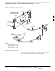
The primary function of the Clock Synchronization Manager (CSM)
boards (slots 1 and 2) is to maintain CDMA system time. The CSM in
slot 1 is the primary timing source while slot 2 provides redundancy.
The CSM2 card (CSM second generation) is required when using the
remote GPS receiver (R–GPS). R–GPS uses a GPS receiver in the
antenna head that has a digital output to the CSM2 card. CSM2 can have
a daughter card as a local GPS receiver to support an RF–GPS signal.
The CSM2 switches between the primary and redundant units (slots 1
and 2) upon failure or command. CDMA Clock Distribution Cards
(CCDs) buffer and distribute even–second reference and 19.6608 MHz
clocks. CCD 1 is married to CSM 1 and CCD 2 is married to CSM 2. A
failure on CSM 1 or CCD 1 cause the system to switch to redundant
CSM 2 and CCD 2.
Each CSM2 board features an ovenized, crystal oscillator that provides
19.6608 MHz clock, even second pulse, and 3 MHz referenced to the
selected synchronization source (see Table 3-19):
GPS: local/RF–GPS or remote/R–GPS
LORAN–C Frequency Receiver (LFR) or High Stability Oscillator
(HSO)
External reference oscillator sources
Fault management has the capability of switching between the GPS
synchronization source and the LFR/HSO backup source in the event of
a GPS receiver failure on CSM 1. During normal operation, the CSM 1
board selects GPS as the primary source (see Table 3-19). The source
selection can also be overridden via the LMF or by the system software.
Synchronization between the primary and redundant CSM CCD pairs, as
well as the LFR or HSO back–up to GPS synchronization, increases
reliability.
Low Frequency Receiver/
High Stability Oscillator
The CSM handles the overall configuration and status monitoring
functions of the LFR/HSO. In the event of GPS failure, the LFR/HSO is
capable of maintaining synchronization initially established by the GPS
reference signal.
The LFR requires an active external antenna to receive LORAN RF
signals. Timing pulses are derived from this signal, which is
synchronized to Universal Time Coordinates (UTC) and GPS time. The
LFR can maintain system time indefinately after initial GPS lock.
3