
User's Manual Part 2

Preparing the LMF – continued
DRAFT
Apr 2001
3-19
SC4812ET BTS Optimization/ATP — CDMA LMF
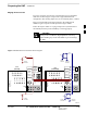
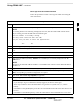
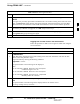
Pinging the Processors
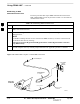
For proper operation, the integrity of the Ethernet LAN A and B links
must be be verified. Figure 3-5 represents a typical BTS Ethernet
configuration. The drawing depicts one (of two identical) links, A and B.
Ping is a program that sends request packets to the LAN network
modules to get a response from the specified “target” module.
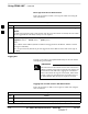
Follow the steps in Table 3-7 to ping each processor (on both LAN A
and LAN B) and verify LAN redundancy is working properly.
Always wear a conductive, high impedance wrist strap
while handling any circuit card/module to prevent damage
by ESD.
CAUTION
RF Expansion Ports
Punch
Block
Power Input
27V Ret
Antenna’s
1A 2A 3A 1B 2B 3B
4A 5A 6A 4B 5B 6B
1A 2A 3A 1B 2B 3B
4A 5A 6A 4B 5B 6B
1
2
Remote
ASU
GND
Lugs
50 Pair
(Alarms/
Punchblock
20 Pair
(RGPS)
RGD
Board
RGD/RGPS
Power Input
+27V
Micro–
wave
RF
GPS
A
B
IN OUT
LAN
19 MHz
2 Sec
Spans
Alams
Modem
Spans)
CHASSIS
GROUND
SIGNAL
GROUND
50Ω
SIGNAL
GROUND
50Ω
IN
BTS
(MASTER)
OUT
BTS
(EXPANSION)
CHASSIS
GROUND
SIGNAL
GROUND
50Ω
SIGNAL
GROUND
50Ω
FW00199
Figure 3-5: BTS Ethernet LAN Interconnect Diagram
3