
User's Manual Part 2

Preparing the LMF – continued
DRAFT
Apr 2001
3-17
SC4812ET BTS Optimization/ATP — CDMA LMF
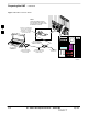
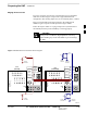
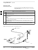
LMF to BTS Connection
The LMF is connected to the LAN A or B connector located on the left
side of the frame’s lower air intake grill, behind the LAN Cable Access
door (see Figure 3-4).
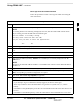
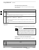
Table 3-6: LMF to BTS Connection
Step Action
1 To gain access to the connectors, open the LAN Cable Access door, then pull apart the Velcro tape
covering the BNC “T” connector and slide out the computer service tray, if desired (see Figure 3-4).
2
Connect the LMF to the LAN A BNC connector via PCMCIA Ethernet Adapter with an unshielded
twisted–pair (UTP) Adapter and 10BaseT/10Base2 converter (powered by an external AC/DC
transformer). If there is no login response, connect the LMF to the LAN B BNC connector. If there is
still no login response, see Table 6-1, Login Failure Troubleshooting Procedure.
NOTE
– Xircom Model PE3–10B2 or equivalent can also be used to interface the LMF Ethernet
connection to the frame connected to the PC parallel port, powered by an external AC/DC
transformer. In this case, the BNC cable must not exceed 91 cm (3 ft) in length.
* IMPORTANT
The LAN shield is isolated from chassis ground. The LAN shield (exposed portion of BNC connector)
must not touch the chassis during optimization.
3