
User's Manual Part 1

Optimization Overview – continued
Apr 2001
1-7
SC4812ET BTS Optimization/ATP — CDMA LMF
DRAFT
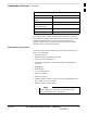
Test Equipment List
The following pieces of test equipment are required during the
optimization procedure. Common assorted tools like screwdrivers and
frame keys are not listed but are still required. Read the owner’s manual
on all of the following major pieces of test equipment to understand their
individual operation prior to use in optimization.
Always refer to specific OEM test equipment
documentation for detailed operating instructions.
NOTE
10BaseT/10Base2 Converter
Ethernet LAN transceiver (part of CGDSLMFCPQ1700)
PCMCIA Ethernet Adpater + Ethernet UTP adapter: 3COM model –
Etherlink III 3C589B
Transition Engineering model E–CX–TBT–03 10BaseT/10Base2
converter
Xircom model PE3–10B2 or equivalent can also be used to
interface the LMF Ethernet connection to the frame.
NOTE
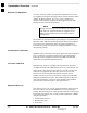
RS–232 to GPIB Interface
National Instruments GPIB–232–CT with Motorola CGDSEDN04X
RS232 serial null modem cable (see Figure 1-1) or equivalent; used to
interface the LMF to the test equipment.
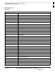
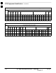
Standard RS–232 cable can be used with the following modifications:
– This solution passes only the 3 minimum electrical connections
between the LMF and the GPIB interface. The control signals are
jumpered as enabled on both ends of the RS–232 cable (9–pin D).
TX and RX signals are crossed as null modem effect. Pin 5 is the
ground reference.
– Short pins 7 and 8 together, and short pins 1, 4, and 6 together on
each connector.
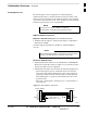
Figure 1-1: Null Modem Cable Detail
5
3
2
7
8
1
4
6
GND
RX
TX
RTS
CTS
RSD/DCD
DTR
GND
TX
RX
RTS
CTS
RSD/DCD
DTR
ON BOTH CONNECTORS
SHORT PINS 7, 8;
SHORT PINS 1, 4, & 6
9–PIN D–FEMALE 9–PIN D–FEMALE
5
2
3
7
8
1
4
6
DSR
DSR
FW00362
1