
User's Manual Part 2

Test Set Calibration – continued
DRAFT
SCt4812T CDMA BTS Optimization/ATP
Mar 2001
3-60
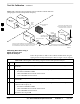
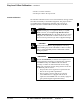
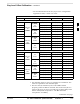
Figure 3-17: Calibrating Test Equipment Setup for TX BLO and TX ATP Tests
(using Signal Generator and Spectrum Analyzer)
50 OHM
TERMINATION
30 DB
DIRECTIONAL
COUPLER
Spectrum
Analyzer
Signal
Generator
A
Spectrum
Analyzer
40W NON–RADIATING
RF LOAD
B
SHORT TEST CABLE
Signal
Generator
THIS WILL BE THE CONNECTION TO THE HP8481A POWER
SENSOR DURING TX BAY LEVEL OFFSET TEST AND TO THE
PCS INTERFACE BOX INPUT PORT DURING TX ATP TESTS.
SHORT
TEST
CABLE
THIS WILL BE THE CONNECTION TO
THE TX PORTS DURING TX BAY LEVEL
OFFSET TEST AND TX ATP TESTS.
CABLE FROM 20 DB @ 20W ATTENUATOR TO THE
PCS INTERFACE OR THE HP8481A POWER SENSOR.
A
ONE 20DB 20 W IN
LINE ATTENUATOR
FW00293
Calibrating RX Cables Using a
Signal Generator and
Spectrum Analyzer
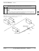
Follow the procedure in Table 3-28 to calibrate the RX cables using the
signal generator and spectrum analyzer. Refer to Figure 3-18, if required.
Table 3-28: Calibrating RX Cables Using a Signal Generator and Spectrum Analyzer
Step Action
1 Connect a short test cable to the spectrum analyzer and connect the other end to the Signal
Generator.
2 Set signal generator to –10 dBm at the customer’s RX frequency of:
– 824–849 for 800 MHz CDMA
– 1850–1910 MHz band for North American PCS
– 1750–1780 MHz for Korean PCS
3 Use spectrum analyzer to measure signal generator output (see Figure 3-18, A) and record the
value for A.
4 Connect the test setup, as shown in the lower portion of the diagram to measure the output at the
customer’s RX frequency of:
– 824–849 for 800 MHz CDMA
– 1850–1910 MHz band for North American PCS
– 1750–1780 MHz for Korean PCS
Record the value at point B.
. . . continued on next page
3