
User's Manual Part 2

Test Set Calibration – continued
DRAFT
Mar 2001
3-59
SCt4812T CDMA BTS Optimization/ATP
Calibrating TX Cables Using a
Signal Generator and
Spectrum Analyzer
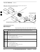
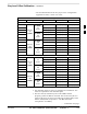
Follow the procedure in Table 3-27 to calibrate the TX cables using a
signal generator and spectrum analyzer. Refer to Figure 3-17 for a
diagram of the signal generator and spectrum analyzer.
Table 3-27: Calibrating TX Cables Using Signal Generator and Spectrum Analyzer
Step Action
1 Connect a short test cable between the spectrum analyzer and the signal generator.
2 Set signal generator to 0 dBm at the customer frequency of:
– 869–894 MHz for 800 MHz CDMA
– 1930–1990 MHz for North American PCS.
– 1840–1870 MHz for KoreaN PCS
3 Use a spectrum analyzer to measure signal generator output (see Figure 3-17, A) and record the
value.
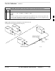
4 Connect the spectrum analyzer’s short cable to point B, (as shown in the lower right portion of the
diagram) to measure cable output at customer frequency of:
– 869–894 MHz for 800 MHz CDMA
– 1930–1990 MHz for North American PCS.
– 1840–1870 MHz for Korean PCS
Record the value at point B.
5 Calibration factor = A – B
Example: Cal = –1 dBm – (–53.5 dBm) = 52.5 dB
NOTE
The short cable is used for calibration only. It is not part of the final test setup. After calibration is
completed, do not re-arrange any cables. Use the equipment setup, as is, to ensure test procedures
use the correct calibration factor.
3