
User's Manual Part 2

CSM System Time/GPS and LFR/HSO Verification – continued
Mar 2001
3-39
SCt4812T CDMA BTS Optimization/ATP
DRAFT
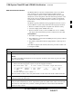
Table 3-19: GPS Initialization/Verification
Step Action
6
If steps 1 through 5 pass, the GPS is good.
* IMPORTANT
If any of the above mentioned areas fail, verify that:
– If Initial position accuracy is “estimated”
(typical), at least 4 satellites must be tracked and
visible (1 satellite must be tracked and visible if actual lat, log, and height data for this site has
been entered into CDF file).
– If Initial position accuracy is “surveyed”,
position data currently in the CDF file is assumed to be
accurate. GPS will not automatically survey and update its position.
– The GPS antenna is not obstructed or misaligned.
– GPS antenna connector center conductor measures approximately +5 Vdc with respect to the
shield.
– There is no more than 4.5 dB of loss between the GPS antenna OSX connector and the BTS frame
GPS input.
– Any lightning protection installed between GPS antenna and BTS frame is installed correctly.
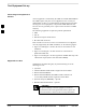
7
Enter the following commands at the CSM> prompt to verify that the CSM is warmed up and that GPS
acquisition has taken place.
debug dpllp
Observe the following typical response if the CSM is not warmed up (15 minutes from application of
power) (If warmed–up proceed to step 8)
CSM>DPLL Task Wait. 884 seconds left.
DPLL Task Wait. 882 seconds left.
DPLL Task Wait. 880 seconds left. ...........etc.
NOTE
The warm command can be issued at the MMI port used to force the CSM into warm–up, but the
reference oscillator will be unstable.
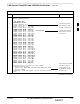
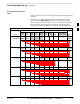
8 Observe the following typical response if the CSM is warmed up.
c:17486 off: –11, 3, 6 TK SRC:0 S0: 3 S1:–2013175,–2013175
c:17486 off: –11
, 3, 6 TK SRC:0 S0: 3 S1:–2013175,–2013175
c:17470 off: –11
, 1, 6 TK SRC:0 S0: 1 S1:–2013175,–2013175
c:17486 off: –11
, 3, 6 TK SRC:0 S0: 3 S1:–2013175,–2013175
c:17470 off: –11
, 1, 6 TK SRC:0 S0: 1 S1:–2013175,–2013175
c:17470 off: –11
, 1, 6 TK SRC:0 S0: 1 S1:–2013175,–2013175
9 Verify the following GPS information (underlined text above, from left to right):
– Lower limit offset from tracked source variable is not less than –60 (equates to 3µs limit).
– Upper limit offset from tracked source variable is not more than +60 (equates to 3µs limit).
– TK SRC: 0 is selected, where SRC 0 = GPS.
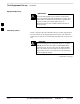
10 Enter the following commands at the CSM> prompt to exit the debug mode display.
debug dpllp
3