
User's Manual Part 2

CSM System Time/GPS and LFR/HSO Verification – continued
Mar 2001
3-35
SCt4812T CDMA BTS Optimization/ATP
DRAFT
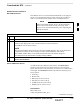
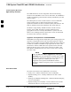
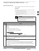
Null Modem Cable
A null modem cable is required. It is connected between the LMF
COM1 port and the RS232–GPIB Interface box. Figure 3-8 shows the
wiring detail for the null modem cable.
Figure 3-8: Null Modem Cable Detail
5
3
2
7
8
1
4
6
GND
RX
TX
RTS
CTS
RSD/DCD
DTR
GND
TX
RX
RTS
CTS
RSD/DCD
DTR
ON BOTH CONNECTORS
SHORT PINS 7, 8;
SHORT PINS 1, 4, & 6
9–PIN D–FEMALE 9–PIN D–FEMALE
5
2
3
7
8
1
4
6
DSR
DSR
FW00362
Prerequisites
Ensure the following prerequisites have been met before proceeding:
The LMF is NOT logged into the BTS.
The COM1 port is connected to the MMI port of the primary CSM via
a null modem board.
CSM Frequency Verification
The objective of this procedure is the initial verification of the CSM
boards before performing the rf path verification tests. Parts of this
procedure will be repeated for final verification after the overall
optimization has been completed.
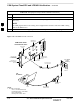
Test Equipment Setup: GPS &
LFR/HSO Verification
Follow the procedure in Table 3-18 to set up test equipment while
referring to Figure 3-9 as required.
Table 3-18: Test Equipment Setup (GPS & LFR/HSO Verification)
Step Action
1 Perform one of the following operations:
– For local GPS (RF–GPS), verify a CSM board with a GPS receiver is installed in primary CSM
slot 1 and that CSM–1 is INS.
NOTE
This is verified by checking the board ejectors for kit number SGLN1145 on the board in slot 1.
– For Remote GPS (RGPS), verify a CSM2 board is installed in primary slot 1 and that CSM–1 is
INS
NOTE
This is verified by checking the board ejectors for kit number SGLN4132CC (or subsequent).
2 Remove CSM–2 (if installed) and connect a serial cable from the LMF COM 1 port (via null modem
board) to the MMI port on CSM–1.
. . . continued on next page
3