
User's Manual Part 2

Preparing the LMF – continued
DRAFT
SCt4812T CDMA BTS Optimization/ATP
Mar 2001
3-14
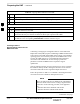
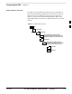
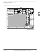
Pinging the Processors
For proper operation, the integrity of the Ethernet LAN A and B links
must be be verified. Figure 3-4 represents a typical BTS Ethernet
configuration. The drawing depicts one (of two identical) links, A and B.
Ping is a program that routes request packets to the LAN network
modules to obtain a response from the specified “targeted” BTS.
Figure 3-4: BTS LAN Interconnect Diagram
CHASSIS
GROUND
SIGNAL
GROUND
50Ω
SIGNAL
GROUND
50Ω
IN
LMF CONNECTOR
B
C–CCP
CAGE
AB
IN
A
B
A
OUT
OUT
BTS
(EXPANSION)
B
C–CCP
CAGE
AB
IN
A
B
A
OUT
BTS
(MASTER)
IN
OUT
FW00141
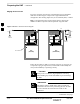
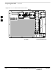
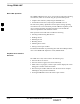
Follow the procedure in Table 3-6 and refer to Figure 3-5 or Figure 3-6,
as required, to ping each processor (on both LAN A and LAN B) and
verify LAN redundancy is operating correctly.
Always wear a conductive, high impedance wrist strap
while handling any circuit card/module to prevent damage
by ESD.
CAUTION
*
The Ethernet LAN A and B cables must be installed on
each frame/enclosure before performing this test. All other
processor board LAN connections are made via the
backplanes.
IMPORTANT
. . . continued on next page
3