
User's Manual Part 2

Isolate Span Lines/Connect LMF – continued
Mar 2001
3-5
SCt4812T CDMA BTS Optimization/ATP
DRAFT
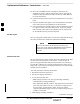
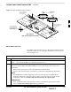
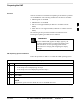
Figure 3-1: Span I/O Board T1 Span Isolation
50–PIN TELCO
CONNECTORS
REMOVED
SPAN A CONNECTOR
(TELCO) INTERFACE
TO SPAN LINES
SPAN B CONNECTOR
(TELCO) INTERFACE
TO SPAN LINES
TOP of Frame
(Site I/O and Span I/O boards)
RS–232 9–PIN SUB D
CONNECTOR SERIAL
PORT FOR EXTERNAL
DIAL UP MODEM
CONNECTION (IF USED)
FW00299
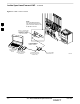
LMF to BTS Connection
The LMF is connected to the LAN A or B connector located on the left
side of the frame’s lower air intake grill, behind the LAN Cable Access
door (see Figure 3-2).
Table 3-2: LMF to BTS Connection
Step Action
1 To gain access to the connectors on the BTS, open the LAN Cable Access door, then pull apart the
Velcro tape covering the BNC “T” connector (see Figure 3-2).
2 Connect the LMF to the LAN A BNC connector via PCMCIA Ethernet Adapter with an unshielded
twisted–pair (UTP) Adapter and 10BaseT/10Base2 converter (powered by an external AC/DC
transformer).
– If there is no login response, connect the LMF to the LAN B connector.
– If there is still no login response, see Table 6-1, Login Failure Troubleshooting Procedures.
NOTE
– Xircom Model PE3–10B2 or equivalent can also be used to interface the LMF Ethernet
connection to the frame connected to the PC parallel port, powered by an external AC/DC
transformer. In this case, the BNC cable must not exceed 91 cm (3 ft) in length.
* IMPORTANT
– The LAN shield is isolated from chassis ground. The LAN shield (exposed portion of BNC
connector) must not touch the chassis during optimization.
3