
User's Manual Part 2

Initial Power–up Tests – continued
Mar 2001
2-15
SCt4812T CDMA BTS Optimization/ATP
DRAFT
Table 2-7: Initial Power–up (BTS)
Step Action
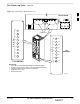
5 Seat the first equipped LPA module pair into the assigned slot in the upper LPA shelf including LPA
fan.
In +27 V systems, observe that the LPA internal fan comes on line.
6 Repeat step 5 for all remaining LPAs.
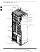
7 Set the LPA breakers to the ON position (per configuration) by pushing them IN one at a time. See
Figure 1-13 on page 1-30 or Figure 1-14 on page 1-31 for configurations and Figure 2-3 on page 2-7
or Figure 2-5 on page 2-9 for LPA breaker panel layout.
On +27 V frames, engage (push) LPA circuit breakers.
Confirm LEDs on LPAs light.
On –48 V frames, engage (push) LPA PS circuit breakers.
Confirm LPA PS fans start.
Confirm LEDs on –48 V power converter boards light.
Confirm LPA fans start.
Confirm LEDs on LPAs light.
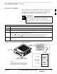
8 After all cards/modules have been seated and verified, use a digital voltmeter to verify power supply
output voltages at the top of the frame remain within specifications: +27.0 Vdc or –48 Vdc
nominal.
9 Repeat Steps 1 through 8 for additional co–located frames (if equipped).
2