
User's Manual Part 2

Initial Power–up Tests
DRAFT
SCt4812T CDMA BTS Optimization/ATP
Mar 2001
2-12
Power-up Procedures
Potentially lethal voltage and current levels are routed to
the BTS equipment. This test must be performed with a
second person present, acting in a safety role. Remove all
rings, jewelry, and wrist watches prior to beginning this
test.
WARNING
DC Input Power
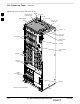
In the tests to follow, power will first be verified at the input to each
BTS frame. After power is verified, cards and modules within the frame
itself will be powered up and verified one at a time.
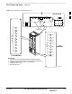
Before applying any power, verify the correct power feed and return
cables are connected between the power supply breakers and the power
connectors at the top of each BTS frame. Verify correct cable position
referring to Figure 2-3 on page 2-7 for +27 V systems and Figure 2-5 on
page 2-9 for –48 V systems.
Always wear a conductive, high impedance wrist strap
while handling any circuit card/module to prevent damage
by ESD. Extreme care should be taken during the removal
and installation of any card/module. After removal, the
card/module should be placed on a conductive surface or
back into the anti–static bag in which it was shipped.
CAUTION
For positive power applications (+27 V):
The positive power cable is red.
The negative power cable (ground) is black.
For negative power applications (–48 V):
The negative power cable is red or blue.
The positive power cable (ground) is black.
In all cases, the black power cable is at ground potential.
IMPORTANT
*
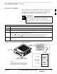
Motorola recommends that the DC input power cable used to connect the
frame to the main DC power source conforms to the guidelines outlined
in Table 2-4.
. . . continued on next page
2