
User's Manual Part 2

Pre–Power–up Tests – continued
Mar 2001
2-11
SCt4812T CDMA BTS Optimization/ATP
DRAFT
DC Power Pre-test (RFDS)
Before applying power to the RFDS, follow the steps in Table 2-3, while
referring to Figure 2-7, to verify there are no shorts in the RFDS DC
distribution system, backplanes, or modules/boards. As of the date of
this publication, the RFDS is not used with the –48 V BTS.
Visual inspection of card placement and equipage for each
frame vs. site documentation must be completed, as
covered in Table 2-1, on page 2-2, before proceeding with
this test.
IMPORTANT
*
Table 2-3: DC Power Pre-test (RFDS)
Step Action
1 Physically verify that all DC/DC converters supplying the RFDS are OFF or disabled.
2 Set the input power rocker switch P1 to the OFF position (see Figure 2-7).
3 Verify the initial resistance from the power (+ or –) feed terminal with respect to ground terminal
measures >
5 kΩ , then slowly begins to increase.
If the initial reading is < 5 kΩ and remains constant, a short exists somewhere in the DC
distribution path supplied by the breaker. Isolate the problem before proceeding.
4 Set the input power rocker switch P1 to the ON position.
Repeat Step 3.
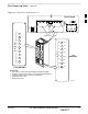
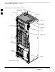
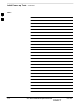
Figure 2-7: DC Distribution Pre-test (COBRA RFDS Detail)
NOTE:
Set the input power switch ON while measuring the
resistance from the DC power – with respect to the
power + terminal on the rear of the COBRA RFDS.
INPUT POWER
SWITCH (P1)
FRONT OF COBRA RFDS
(cut away view shown for clarity)
RFDS REAR
INTERCONNECT PANEL
“–” CONNECTOR
PIN
“+” CONNECTOR
PIN
CONNECTOR (MADE
UP OF A HOUSING
AND TWO PINS)
FW00139
2