
User's Manual

Isolate Span Lines/Connect LMF – continued
May 2000
3-5
SC 4812T CDMA BTS Optimization/ATP
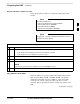
LMF to BTS Connection
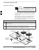
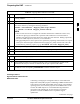
The LMF is connected to the LAN A or B connector located on the left
side of the frame’s lower air intake grill, behind the LAN Cable Access
door (see Figure 3-2).
Table 3-2: LMF to BTS Connection
Step Action
1 To gain access to the connectors on the BTS, open the LAN Cable Access door, then pull apart the
Velcro tape covering the BNC “T” connector (see Figure 3-2).
2 Connect the LMF to the LAN A BNC connector via PCMCIA Ethernet Adapter with an unshielded
twisted–pair (UTP) Adapter and 10BaseT/10Base2 converter (powered by an external AC/DC
transformer).
NOTE
– Xircom Model PE3–10B2 or equivalent can also be used to interface the LMF Ethernet
connection to the frame connected to the PC parallel port, powered by an external AC/DC
transformer. In this case, the BNC cable must not exceed 91 cm (3 ft) in length.
* IMPORTANT
– The LAN shield is isolated from chassis ground. The LAN shield (exposed portion of BNC
connector) must not touch the chassis during optimization.
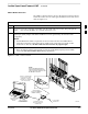
Figure 3-2: LMF Connection Detail
NOTE:
Open LAN CABLE ACCESS
door. Pull apart Velcro tape and
gain access to the LAN A or LAN
B LMF BNC connector.
LMF BNC “T” CONNECTIONS
ON LEFT SIDE OF FRAME
(ETHERNET “A” SHOWN;
ETHERNET “B” COVERED
WITH VELCRO TAPE)
Á
Á
Á
Á
LMF COMPUTER
TERMINAL WITH
MOUSE
PCMCIA ETHERNET
ADPATER & ETHERNET
UTP ADAPTER
10BASET/10BASE2
CONVERTER
CONNECTS
DIRECTLY TO BNC T
115 VAC POWER
CONNECTION
Á
FW00140
Á
UNIVERSAL TWISTED
PAIR (UTP) CABLE (RJ11
CONNECTORS)
3