
User's Manual

Isolate Span Lines/Connect LMF
SC 4812T CDMA BTS Optimization/ATP
May 2000
3-4
Isolate BTS from T1/E1 Spans
At active sites, the OMC/CBSC must disable the BTS and
place it out of service (OOS). DO NOT remove the 50–pin
TELCO cable connected to the BTS frame site I/O board
J1 connector until the OMC/CBSC has disabled the BTS!
IMPORTANT
*
Each frame is equipped with one Site I/O and two Span I/O boards. The
Span I/O J1 connector provides connection of 25 pairs of wire. 8 pairs
are used to support up to four 4–wire span lines. 17 pairs are connected
to signal ground.
Before connecting the LMF to the frame LAN, the OMC/CBSC must
disable the BTS and place it OOS to allow the LMF to control the
CDMA BTS. This prevents the CBSC from inadvertently sending
control information to the CDMA BTS during LMF based tests. Refer to
Figure 3-1 and Figure 3-2 as required.
Table 3-1: T1/E1 Span Isolation
Step Action
1 From the OMC/CBSC, disable the BTS and place it OOS. Refer to SC OMC–R/CBSC System
Operator Procedures.
– The T1/E1 span 50–pin TELCO cable connected to the BTS frame SPAN I/O board J1 connector
can be removed from both Span I/O boards, if equipped, to isolate the spans.
* IMPORTANT
Verify that you remove the SPAN cable, not the “MODEM/TELCO” connector.
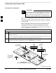
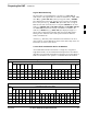
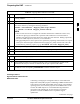
Figure 3-1: Span I/O Board T1 Span Isolation
50–PIN TELCO
CONNECTORS
REMOVED
SPAN A CONNECTOR
(TELCO) INTERFACE
TO SPAN LINES
SPAN B CONNECTOR
(TELCO) INTERFACE
TO SPAN LINES
TOP OF frame
(Site I/O and Span I/O boards)
RS–232 9–PIN SUB D
CONNECTOR SERIAL
PORT FOR EXTERNAL
DIAL UP MODEM
CONNECTION (IF USED)
FW00299
. . . continued on next page
3