
User's Manual
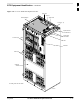
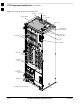

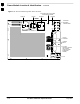

Frame Module Location & Identification – continued
SC 4812T CDMA BTS Optimization/ATP
May 2000
1-24
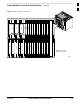
LPA1A
LPA1B
LPA1C
LPA1D
LPA3A
LPA3B
LPA3C
LPA3D
LPA2A
LPA2B
LPA2C
LPA2D
LPA4A
LPA4B
LPA4C
LPA4D
FAN
MODULE
(TYPICAL)
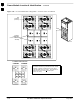
FILTERS /
COMBINERS
(2 TO 1 COMBINER
SHOWN)
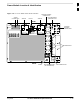
Note
No adjacent carriers may exist within the same TX filter
combiner. “Adjacent” is defined as f
c1
and f
c2
being
1.25 MHz apart (center–to–center). “Non–adjacent” is
defined as f
c1
and f
c2
being >2.50 MHz apart
(center–to–center).
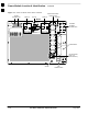
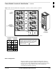
123
456
4–CARRIER CONFIGURATION
CARRIER
1
3
CARRIER
2
4
123
456
FW00296
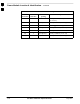
Figure 1-11: +27 V SC 4812T LPA Configuration – 4 Carrier with 2:1 Combiners
1