
User's Manual

BTS Equipment Identification – continued
May 2000
1-13
SC 4812T CDMA BTS Optimization/ATP
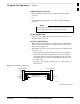
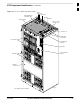
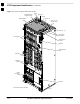
Top Interconnect Plate (see Figure 1-6 or Figure 1-7)
All cabling to and from the BTS equipment frames is via the
interconnect panel on the top of each frame. Connections made here
include:
Span lines
RX antennas
TX antenna
Alarm connections
Power input
LAN connections
GPS input
Remote GPS Distribution (RGD)
LFR input
Expansion frame connection
Ground connections
C–CCP Shelf (see Figure 1-10)
C–CCP backplane and cage
Power supply modules
CDMA clock distribution (CCD) boards
CSM and HSO/LFR boards
Alarm Monitoring and Reporting (AMR) boards
Group Line Interface II (GLI2) cards
Multicoupler Preselector (MPC) boards (starter frame only)
Expansion Multicoupler Preselector (EMPC) boards (expansion
frames)
Switch card
MCC24 boards
MCC8E boards
BBX2 boards
CIO boards
PA Shelves (see Figure 1-11 or Figure 1-12)
LPA cages
LPA trunking backplanes
Single Tone Linear Power Amplifier (STLPA, or more commonly
referred to as “LPA”) modules
LPA fan modules
LPA Combiner Cage (+27 V BTS)
TX filter combiners or bandpass filters
. . . continued on next page
1