
User's Manual

BTS Equipment Identification
SC 4812T CDMA BTS Optimization/ATP
May 2000
1-12
Frames
The Motorola SC 4812T BTS can consist of the following equipment
frames:
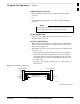
At least one BTS starter frame
– +27 V BTS (see Figure 1-2)
– –48V BTS (see Figure 1-3)
Ancillary equipment frame (or wall mounted equipment)
Expansion frames
– +27 V BTS (see Figure 1-4)
– –48V BTS (see Figure 1-5)
Ancillary Equipment Frame
Identification
Equipment listed below can be wall mounted or mounted
in a standard 19 inch frame. The description assumes that
all equipment is mounted in a frame for clarity.
NOTE
If equipped with the RF Diagnostic Subsystem (RFDS) option, the
RFDS and directional couplers are the interface between the site
antennas and the BTS or Modem frame. The RFDS equipment includes:
Directional couplers
Site receive bandpass/bandreject filters
RFDS
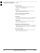
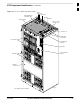
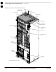
BTS Frame Description
The BTS is the interface between the span lines to/from the Cellsite Base
Station Controller (CBSC) and the site antennas. This frame is described
in three sections:
The top interconnect plate where all connections are made.
The upper portion of the frame which houses circuit breakers, cooling
fans, and the Combined CDMA Channel Processor (C–CCP) shelf.
The lower portion of the frame which houses the LPA fans, LPAs, and
TX filter/combiners.
The –48 V version of the BTS also has a section below the LPAs
containing a power conversion shelf that supplies power to the LPAs.
Use the illustrations that follow to visually identify the major
components, that make up the Motorola SC 4812T BTS frame.
. . . continued on next page
1