
User's Manual

Required Test Equipment – continued
May 2000
1-7
SC 4812T CDMA BTS Optimization/ATP
10BaseT/10Base2 Converter
Transition Engineering Model E–CX–TBT–03 10BaseT/10Base2
Converter
– or –
Transition Engineering Model E–CX–TBT–03 10BaseT/10Base2
Converter
Xircom Model PE3–10B2 or equivalent can also be used to
interface the LMF Ethernet connection to the frame.
NOTE
3C–PC–COMBO CBL
Connects to the 3COM PCMCIA card and eliminates the need for a
10BaseT/10base2 Converter.
RS–232 to GPIB Interface
National Instruments GPIB–232–CT with Motorola CGDSEDN04X
RS232 serial null modem cable or equivalent; used to interface the
LMF to the test equipment.
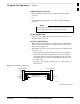
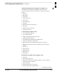
Standard RS–232 cable can be used with the following modifications
(see Figure 1-1):
– This solution passes only the 3 minimum electrical connections
between the LMF and the GPIB interface. The control signals are
jumpered as enabled on both ends of the RS–232 cable (9–pin D).
TX and RX signals are crossed as Null Modem effect. Pin 5 is the
ground reference.
– Short pins 7 and 8 together, and short pins 1, 4, and 6 together on
each connector.
Figure 1-1: Null Modem Cable Detail
5
3
2
7
8
1
4
6
GND
RX
TX
RTS
CTS
RSD/DCD
DTR
GND
TX
RX
RTS
CTS
RSD/DCD
DTR
ON BOTH CONNECTORS
SHORT PINS 7, 8;
SHORT PINS 1, 4, & 6
9–PIN D–FEMALE 9–PIN D–FEMALE
5
2
3
7
8
1
4
6
DSR
DSR
FW00362
. . . continued on next page
1