
User's Manual

Transmit & Receive Antenna VSWR – continued
SC 4812T CDMA BTS Optimization/ATP
May 2000
G-6
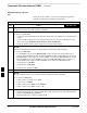
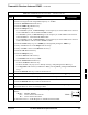
Table G-2: VSWR Measurement Procedure – Advantest Test Set
Step ADVANTESTAction
9 If the readings indicate a potential problem, verify the physical integrity of all cables (including any
in–line components, pads, etc.) and associated connections up to the antenna. If problem still persists,
consult antenna OEM documentation for additional performance verification tests or replacement
information.
10 Repeat steps 2 through 9 for all remaining TX sectors/antennas.
11 Repeat steps 2 through 9 for all remaining RX sectors/antennas.
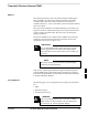
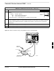
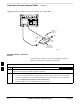
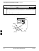
Figure G-3: Manual VSWR Test Setup Using Advantest R3465
RVS
(REFLECTED)
PORT
FEED LINE TO
ANTENNA
UNDER TEST
RF
SHORT
30 DB
DIRECTIONAL
COUPLER
OUTPUT
PORT
FWD (INCIDENT)
PORT 50–OHM
TERMINATED LOAD
INPUT
PORT
RF OUT
RF IN
FW00332
G