
User's Manual


Transmit & Receive Antenna VSWR – continued
SC 4812T CDMA BTS Optimization/ATP
May 2000
G-2
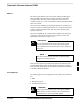
Equipment Setup – HP Test
Set
Follow the steps in Table G-1 to set up test equipment required to
measure and calculate the VSWR for each antenna.
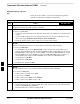
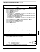
Table G-1: VSWR Measurement Procedure – HP Test Set
Step Action HP TEST SET
1 If you have not already done so, refer to the procedure in Table 3-2 on page 3-5 to set up test
equipment & interface the LMF computer to the BTS.
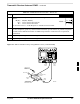
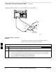
2 For manual VSWR testing, using external directional coupler, refer to Figure G-1 (1700/1900 MHz)
or Figure G-2 (800 MHz).
– Connect the communications test set RF OUT ONLY port to the INPUT port of the directional
coupler.
– Connect the RF IN/OUT port of the communication test set to the reverse (RVS) port on the
directional coupler. Terminate the forward port with a 50 ohm load.
– Install the antenna feed line to the output port on the directional coupler.
NOTE
Manual Communications Analyzer test setup (fields not indicated remain at default):
Set screen to RF GEN.
– For 1900 MHz systems, set the RF Gen Freq to center frequency of actual CDMA carrier
between 1930–1990 MHz for TX and 1850–1910 MHz for RX. For 800 MHz systems, set the
RF Gen Freq to center frequency of actual CDMA carrier between 869–894 MHz for TX and
824–849 MHz for RX. For 1700 MHz systems, set the RF Gen Freq to center frequency of
actual CDMA carrier between 1840–1870 MHz for TX and 1750–1780 MHz for RX.
– Set Amplitude to –30 dBm.
– Set Output Port to RF OUT.
– Set AFGen1 & AFGen2 to OFF.
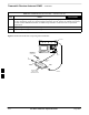
3 Remove the antenna feed line and install an “RF short” onto the directional coupler output port.
NOTE
Set–up communication test set as follows (fields not indicated remain at default):
Set screen to SPEC ANL.
– Under Controls, set input port to ANT.
–
Set Ref Level to –40 dBm.
– Under Controls, select Main, select Auxiliary.
– Under Controls, select AV G . Set Avg = 20.
4 – Record the reference level on the communications analyzer and Note as P
S
for reference.
– Replace the short with the antenna feedline. Record the reference level on the communications
analyzer and Note for as P
A
reference.
– Record the difference of the two readings in dB.
. . . continued on next page
G