
User's Manual

Test Equipment Setup – continued
May 2000
F-5
SC 4812T CDMA BTS Optimization/ATP
Table F-2: Manual Cable Calibration Test Equipment Setup (using the HP PCS Interface)
Step Action
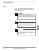
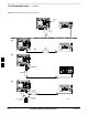
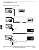
19 After all components are calibrated, reassemble all components together and calculate the total test
setup loss by adding up all the individual losses:
Example: Total test setup loss = –1.4 –29.8 –20.1 = –51.3 dB.
This calculated value will be used in the next series of tests.
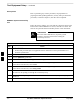
20 Under Screen Controls press the TESTS button to display the TESTS (Main Menu) screen.
21 Select Continue (K2).
22 Select RF Generator Level and set to –119 dBm.
23 Click on Pause for Manual Measurement.
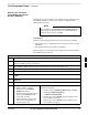
24 Verify the HP8921A Communication Analyzer/83203A CDMA interface setup is as follows (fields
not indicated remain at default):
Verify the GPIB (HP–IB) address:
– under To Screen, select More
– select IO CONFIG
– Set HP–IB Adrs to 18
– set Mode to Talk&Lstn
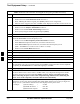
Verify the HP8921A is displaying frequency (instead of RF channel)
– Press the blue
[SHIFT] button, then press the Screen Control [DUPLEX] button; this switches to
the CONFIG (CONFIGURE) screen.
– Use the cursor control to set RF Display to Freq
25 Refer to Table 3-28 for assistance in manually setting the cable loss values into the LMF.
F