
User's Manual


Appendix C: FRU Optimization/ATP Test Matrix – continued
SC 4812T CDMA BTS Optimization/ATP
May 2000
C-2
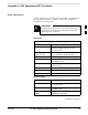
Inter-frame Cabling
Optimization must be performed after the replacement of any RF cabling
between BTS frames.
Table C-2: When to Optimize Inter–frame Cabling
Item Replaced Optimize:
Ancillary frame to BTS
frame (RX) cables
The affected sector/antenna RX
paths.
BTS frame to ancillary frame
(TX) cables
The affected sector/antenna TX paths.
Detailed Optimization/ATP
Test Matrix
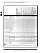
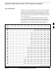
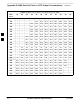
Table C-3 outlines in more detail the tests that would need to be
performed if one of the BTS components were to fail and be replaced. It
is also assumed that all modules are placed OOS–ROM via the LMF
until full redundancy of all applicable modules is implemented.
The following guidelines should also be noted when using this table.
Not every procedure required to bring the site back on line
is indicated in Table C-3. It is meant to be used as a
guideline ONLY. The table assumes that the user is familiar
enough with the BTS Optimization/ATP procedure to
understand which test equipment set ups, calibrations, and
BTS site preparation will be required before performing the
Table # procedures referenced.
IMPORTANT
*
Various passive BTS components (such as the TX and RX directional
couplers, Preselector IO, CIO; etc.) only call for a TX or RX calibration
audit to be performed in lieu of a full path calibration. If the RX or TX
path calibration audit fails, the entire RF path calibration will need to be
repeated. If the RF path calibration fails, further troubleshooting is
warranted.
Whenever any C–CCP BACKPLANE is replaced, it is assumed that
only power to the C–CCP shelf being replaced is turned off via the
breaker supplying that shelf.
Whenever any DISTRIBUTION BACKPLANE is replaced it is assumed
that the power to the entire RFM frame is removed and the Preselector
I/O is replaced. The modem frame should be brought up as if it were a
new installation.
. . . continued on next page
C