
User's Manual

Module Front Panel LED Indicators and Connectors – continued
SC 4812T CDMA BTS Optimization/ATP
May 2000
6-26
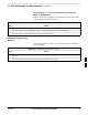
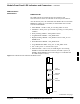
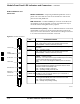
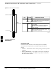
Figure 6-3: MCC24/8E Front Panel
PWR/ALM LED
LENS
(REMOVABLE)
ACTIVE LED
PWR/ALM ACTIVE
PWR/ALM
OFF - operating normally
ON - briefly during powerup and during failure
conditions
ACTIVE
LED
OPERATING STATUS
RAPIDLY BLINKING - Card is codeloaded but
not enabled
SLOW BLINKING - Card is not codeloaded
ON - card is codeloaded and enabled
(INS_ACTIVE)
COLOR
GREEN
RED
RED
ON - fault condition
SLOW FLASHING (alternating with green) - CHI
bus inactive on powerup
An alarm is generated in the event of a failure
FW00224
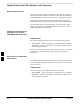
LPA Shelf LED Status
Combinations
LPA Module LED
Each LPA module contains a bi–color LED just above the MMI
connector on the front panel of the module. Interpret this LED as
follows:
GREEN — LPA module is active and is reporting no alarms (Normal
condition).
Flashing GREEN/RED — LPA module is active but is reporting an
low input power condition. If no BBX is keyed, this is normal and
does not constitute a failure.
6