
User's Manual

Module Front Panel LED Indicators and Connectors – continued
May 2000
6-25
SC 4812T CDMA BTS Optimization/ATP
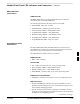
BBX2 LED Status
Combinations
PWR/ALM LED
The BBX module has its own alarm (fault) detection circuitry that
controls the state of the PWR/ALM LED.
The following list describes the states of the bi-color LED:
Solid GREEN – INS_ACT no alarm
Solid RED Red – initializing or power-up alarm
Slowly Flashing GREEN – OOS_ROM no alarm
Long RED/Short GREEN – OOS_ROM alarm
Rapidly Flashing GREEN – OOS_RAM no alarm
Short RED/Short GREEN – OOS_RAM alarm
Long GREEN/Short RED – INS_ACT alarm
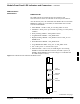
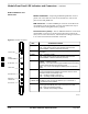
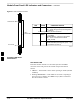
MCC24/8E LED Status
Combinations
The MCC24/MCC8E module has LED indicators and connectors as
described below (see Figure 6-3). Note that the figure does not show the
connectors as they are concealed by the removable lens.
The LED indicators and their states are as follows:
PWR/ALM LED
RED – fault on module
ACTIVE LED
Off – module is inactive, off-line, or not processing traffic.
Slowly Flashing GREEN – OOS_ROM no alarm.
Rapidly Flashing Green – OOS_RAM no alarm.
Solid GREEN – module is INS_ACT, on-line, processing traffic.
PWR/ALM and ACTIVE LEDs
Solid RED – module is powered but is in reset or the BCP is inactive.
MMI Connectors
The RS–232 MMI port connector (four-pin) is intended to be used
primarily in the development or factory environment but may be used
in the field for debugging purposes.
The RJ–11 ethernet port connector (eight-pin) is intended to be used
primarily in the development environment but may be used in the field
for high data rate debugging purposes.
. . . continued on next page
6