
User's Manual

Module Front Panel LED Indicators and Connectors – continued
SC 4812T CDMA BTS Optimization/ATP
May 2000
6-24
GLI2 Pushbuttons and
Connectors
RESET Pushbutton – Depressing the RESET pushbutton causes a
partial reset of the CPU and a reset of all board devices. The GLI2 is
placed in the OOS_ROM state
MMI Connector – The RS–232MMI port connector is intended to be
used primarily in the development or factory environment but may be
used in the field for debug/maintenance purposes.
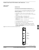
LAN Connectors (A & B) – The two 10BASE2 Ethernet circuit board
mounted BNC connectors are located on the bottom front edge of the
GLI2; one for each LAN interface, A & B. Ethernet cabling is connected
to tee connectors fastened to these BNC connectors.
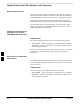
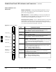
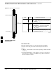
Figure 6-2: GLI2 Front Panel
MMI PORT
CONNECTOR
ACTIVE LED
STATUS RESET ALARM SPANS MASTER MMI ACTIVE
STATUS LED
RESET
PUSHBUTTON
ALARM LED
SPANS LED
MASTER LED
STATUS OFF - operating normally
ON - briefly during powerup when the Alarm LED turns OFF.
SLOW GREEN - when the GLI2 is INS (inservice)
RESET
ALARM OFF - operating normally
ON - briefly during powerup when the Alarm LED turns OFF.
SLOW GREEN - when the GLI2 is INS (inservice)
SPANS
MASTER
MMI PORT
CONNECTOR
ACTIVE
LED OPERATING STATUS
All functions on the GLI2 are reset when pressing and releasing
the switch.
ON - operating normally in active card
OFF - operating normally in standby card
Shows the operating status of the redundant cards. The redundant
card toggles automatically if the active card is removed or fails
ON - active card operating normally
OFF - standby card operating normally
The pair of GLI2 cards include a redundant status. The card in the
top shelf is designated by hardware as the active card; the card in
the bottom shelf is in the standby mode.
OFF - card is powered down, in initialization, or in standby
GREEN - operating normally
YELLOW - one or more of the equipped initialized spans is receiving
a remote alarm indication signal from the far end
RED - one or more of the equipped initialized spans is in an alarm
state
An RS232, serial, asynchronous communications link for use as
an MMI port. This port supports 300 baud, up to a maximum of
115,200 baud communications.
FW00225
6