
User's Manual

Module Front Panel LED Indicators and Connectors – continued
May 2000
6-23
SC 4812T CDMA BTS Optimization/ATP
GLI2 LED Status
Combinations
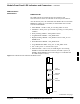
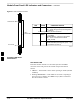
The GLI2 module has indicators, controls and connectors as described
below and shown in Figure 6-2.
The indicators and controls consist of:
Four LEDs
One pushbutton
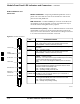
ACTIVE LED
Solid GREEN – GLI2 is active. This means that the GLI2 has shelf
control and is providing control of the digital interfaces.
Off – GLI2 is not active (i.e., Standby). The mate GLI2 should be
active.
MASTER LED
Solid GREEN – GLI2 is Master (sometimes referred to as MGLI2).
Off – GLI2 is non-master (i.e., Slave).
ALARM LED
Solid RED – GLI2 is in a fault condition or in reset.
While in reset transition, STATUS LED is OFF while GLI2 is
performing ROM boot (about 12 seconds for normal boot).
While in reset transition, STATUS LED is ON while GLI2 is
performing RAM boot (about 4 seconds for normal boot).
Off – No Alarm.
STATUS LED
Flashing GREEN– GLI2 is in service (INS), in a stable operating
condition.
On – GLI2 is in OOS RAM state operating downloaded code.
Off – GLI2 is in OOS ROM state operating boot code.
SPANS LED
Solid GREEN – Span line is connected and operating.
Solid RED – Span line is disconnected or a fault condition exists.
6